Electronic Science - Online Test
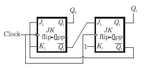
Q1. What are the counting states (Q1,Q2) for the counter shown in the figure below
Answer : Option A
Explaination / Solution:
The given circuit is as follows.
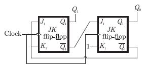
The truth table is as shown below. Sequence is 00, 11, 10, 00 ...
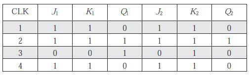
The truth table is as shown below. Sequence is 00, 11, 10, 00 ...
Q2. A function 1 – x2 + x3 is defined in the closed interval [-1, 1]. The value of x , in the open interval (-1, 1) for which the mean value theorem is satisfied, is
Answer : Option B
Explaination / Solution:
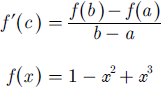
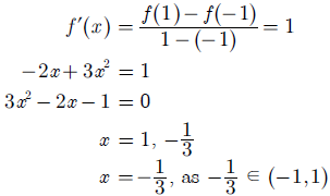
Lagrange’s mean value theorem states that if a function f(x) is continuous in close interval [a, b] and differentiable in open interval (a + b), then for point c in the interval, we may define
Since, polynomial function is always continuous and differentiable, so
Q3. The output F in the digital logic circuit shown in the figure is

Answer : Option A
Explaination / Solution:
In the logic circuit, the two inputs to the output AND gate are


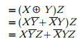
So, we have the output
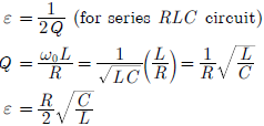
Q4. The damping ratio of a series RLC circuit can be expressed as
Answer : Option C
Explaination / Solution:
Damping ratio is given by
Q5. Consider the Boolean function,  . Which one of the following is the complete set of essential prime implicants ?
. Which one of the following is the complete set of essential prime implicants ?
Answer : Option D
Explaination / Solution:
k -map for the Boolean function can be given as

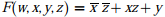
Therefore, the simplified So P from for the Boolean function is
Q6. For maximum power transfer between two cascaded sections of an electrical
network, the relationship between the output impedance Z1 of the first section
to the input impedance Z2 of the second section is
Answer : Option C
Explaination / Solution:
Consider the cascaded network shown below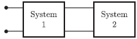
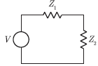
Since, the output impedance of system 1 is Z1 and input impedance of system 2
is Z2. So, we have the equivalent circuit is
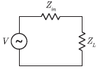
Now, we consider a circuit with internal impedance Zin and load impedance ZL
For maximum power transfer, the condition is
Zin* = Z2
Comparing this condition to cascaded system, we have the required condition for
maximum power transfer as
Z1* = Z2
Q7. The digital logic shown in the figure satisfies the given state diagram when Q1 is
connected to input A of the XOR gate.
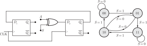
Suppose the XOR gate is replaced by an XNOR gate. Which one of the following
options preserves the state diagram ?
Answer : Option D
Explaination / Solution:
No Explaination.
Q8. Consider the configuration shown in the figure which is a portion of a larger
electrical network
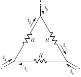
For R = 1Ω and currents i1 = 2 A, i4 =- 1 A, i5 =- 4 A, which one of the
following is TRUE ?
Answer : Option A
Explaination / Solution:
From the circuit, we have
i2 = i4 + i1
= -1 + 2
= 1A
i3 = i5 + i2
= -4 + 1
= -3A
i6 = i1 – i3
= 2 - (-3)
= 5A
Q9.
If segments a to g are considered as functions of P1 and P2, then which of the following is correct
Answer : Option B
Explaination / Solution:
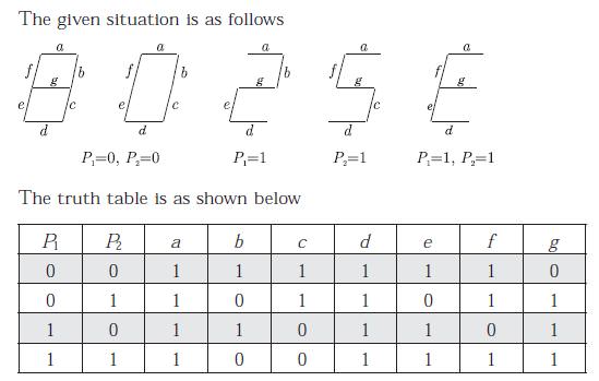
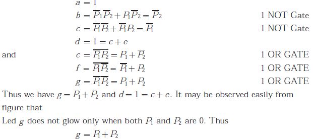
LED d is 1 all condition and also it depends on
d = c + e
Q10. A two-port network has scattering parameters given by  If the
port-2 of the two port is short circuited, the S11 parameter for the resultant one
If the
port-2 of the two port is short circuited, the S11 parameter for the resultant one
If the
port-2 of the two port is short circuited, the S11 parameter for the resultant one
Answer : Option B
Explaination / Solution:
No Explaination.
