Analog Circuits - Online Test
Q1. 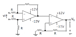
The CORRECT transfer characteristic is
Answer : Option D
Explaination / Solution:
It is a Schmitt trigger and phase shift is zero.
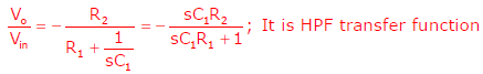
Q2. The circuit shown is a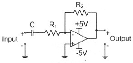
Answer : Option B
Explaination / Solution:
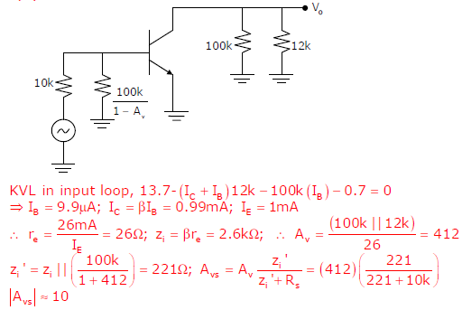
Q3. The voltage gain Av of the circuit shown below is
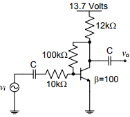
Answer : Option D
Explaination / Solution:
Q4. In the circuit shown below what is the output voltage out (Vout) in Volts if a silicon
transistor Q and an ideal op-amp are used?
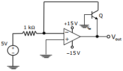
Answer : Option B
Explaination / Solution:
No Explaination.
Q5. In the circuit shown below the op-amps are ideal. Then Vout in Volts is
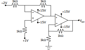
Answer : Option C
Explaination / Solution:
No Explaination.
Q6. 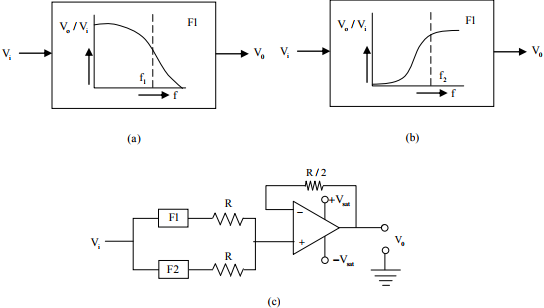
The filters F1 and F2 having characteristics as shown in Figures (a) and (b) are connected as shown in Figure (c).
The cut-off frequencies of F1 and F2 are f1 and f2 respectively. If f1 < f2 the resultant
circuit exhibits the characteristics of a
Answer : Option B
Explaination / Solution:
No Explaination.
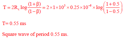
Q7. The saturation voltage of the ideal op-amp shown below is ±10V. The output voltage v0 of
the following circuit in the steady-state is
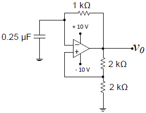
Answer : Option A
Explaination / Solution:

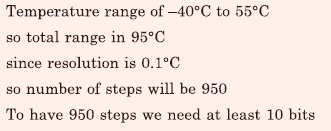
Q8. A temperature in the range of −40˚ C to 55˚ C is to be measured with a resolution of 0.1˚ C. The
minimum number of ADC bits required to get a matching dynamic range of the temperature sensor
Answer : Option B
Explaination / Solution:
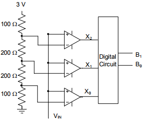
Q9. A 2-bit flash Analog to Digital Converter (ADC) is given below. The input is 0 ≤ VIN ≤ 3 Volts.
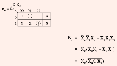
The expression for the LSB of the output B0 as a Boolean function of X2, X1, and X0 is
Answer : Option A
Explaination / Solution:

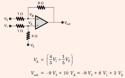
Q10. For the circuit shown below, taking the opamp as ideal, the output voltage Vout in terms of the input
voltages V1 , V2 and V3 is
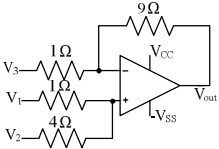
Answer : Option D
Explaination / Solution: