Digital Circuits - Online Test
Q1. The output Y of the logic circuit given below is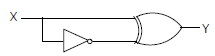
Answer : Option A
Explaination / Solution:
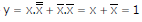
Q2. A low – pass filter with a cut-off frequency of 30Hz is cascaded with a high-pass filter with a cut-off frequency of 20Hz. The resultant system of filters will function as
Answer : Option D
Explaination / Solution:
Q3. A portion of the main program to call a subroutine SUB in an 8085 environment is given below.
:
:
LXI D,DISP
LP : CALL SUB
:
It is desired that control be returned to LP+DISP+3 when the RET instruction is executed in the subroutine. The set of instructions that precede the RET instruction in the subroutine are
Answer : Option C
Explaination / Solution:
No Explaination.
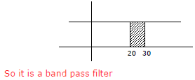
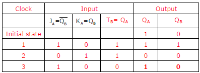
Q4. A two – bit counter circuit is shown below
It the state QAQB of the counter at the clock time tn is ‘10’ then the state QAQB of the counter at tn + 3 (after three clock cycles ) will be
Answer : Option C
Explaination / Solution:
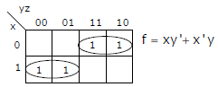
Q5. In the sum of products function f (X, Y, Z) = ∑(2, 3, 4, 5), the prime implicants are
Answer : Option A
Explaination / Solution:
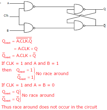
Q6. Consider the given circuit.
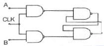
In this circuit, the race around
Answer : Option A
Explaination / Solution:
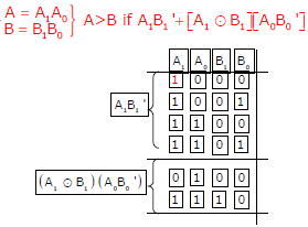
Q7. The output Y of a 2-bit comparator is logic 1 whenever the 2-bit input A is greater than the 2-bit input B. The number of combinations for which the output is logic 1, is
Answer : Option B
Explaination / Solution:
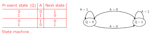
Q8. The state transition diagram for the logic circuit shown is
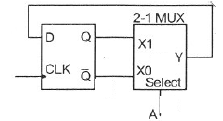
Answer : Option D
Explaination / Solution:
Q9. In the circuit shown below, Q1 has negligible collector-to-emitter saturation
voltage and the diode drops negligible voltage across it under forward bias. If Vcc is +5V, X and Y are digital signals with 0V as logic 0 and Voc as logic 1, then the
Boolean expression for Z is
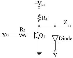
Answer : Option B
Explaination / Solution:
No Explaination.
Q10. 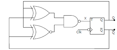
The clock frequency applied to the digital circuit shown in the figure below is 1kHz. If the initial state of the output of the flip-flop is 0, then the frequency of the output waveform Q in kHz is
Answer : Option B
Explaination / Solution:
No Explaination.
