Electrical and Electronic Measurements - Online Test
Q1. 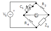
The bridge circuit shown in the figure below is used for the measurement of an
unknown element ZX. The bridge circuit is best suited when ZX is a
Answer : Option C
Explaination / Solution:
Q2. Consider the following statement
(i) The compensating coil of a low power factor wattmeter compensates the effect of the impedance of the current coil.
(ii) The compensating coil of a low power factor wattmeter compensates the effect 0of the impedance of the voltage coil circuit.
Answer : Option B
Explaination / Solution:
No Explaination.
Q3. A  digit DMM has the error specification as : 0.2% of reading + 10 counts. If a dc voltage of 100V is read on its 200V full scale, the maximum error that can be expected in the reading is
Answer : Option C
Explaination / Solution:
No Explaination.
Q4. The bridge method commonly used for finding mutual inductance is
Answer : Option A
Explaination / Solution:
No Explaination.
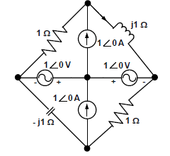
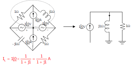
Q5. In the circuit shown below, the current through the inductor is
Answer : Option C
Explaination / Solution:
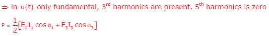
Q6. For the circuit shown in the figure, the voltage and current expressions are 
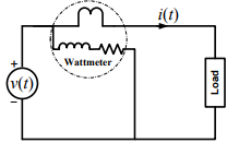
The average power measured by the Wattmeter is
Answer : Option C
Explaination / Solution:
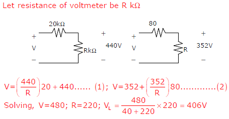
Q7. An analog voltmeter uses external multiplier settings. With a multiplier setting of 20 kΩ it reads
440 V and with a multiplier setting of 80 kΩ it reads 352 V. For a multiplier setting of 40 kΩ the
voltmeter reads
Answer : Option D
Explaination / Solution:
Q8. Three moving iron type voltmeters are connected as shown below. Voltmeter
readings are V, V1 and V2 as indicated. The correct relation among the voltmeter
readings is
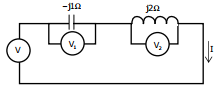
Answer : Option B
Explaination / Solution:
No Explaination.
Q9. 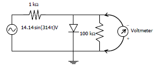
The input impedance of the permanent magnet moving coil (PMMC) voltmeter is infinite. Assuming that the diode shown in the figure below is ideal, the reading of the voltmeter in Volts is
Answer : Option A
Explaination / Solution:
No Explaination.
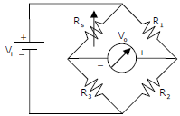
Q10. A strain gauge forms one arm of the bridge shown in the figure below and has a nominal resistance
without any load as Rs = 300 Ω. Other bridge resistances are R1 = R2 = R3 = 300 Ω. The maximum
permissible current through the strain gauge is 20 mA. During certain measurement when the
bridge is excited by maximum permissible voltage and the strain gauge resistance is increased by
1% over the nominal value, the output voltage V0 in mV is
Answer : Option C
Explaination / Solution:
No Explaination.
