Electronic Science - Online Test
Q1.
What are the minimum numbers of NOT gates and 2 - input OR gates required to design the logic of the driver for this 7 - Segment display
Answer : Option D
Explaination / Solution:
As shown in previous solution 2 NOT gates and 3-OR gates are required.
Q2. A 230 V rms source supplies power to two loads connected in parallel. The first load draws 10 kW at 0.8 leading power factor and the second one draws 10 kVA at 0.8 lagging power factor. The complex power delivered by the source is
Answer : Option B
Explaination / Solution:
Consider the circuit diagram for given problem as shown below
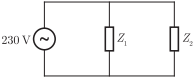
Load delivered to Z1 is
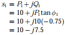
P1 = 10 kW
cos ϕ1
= 0.8, leading
So, we obtain the complex power delivered to Z1 as
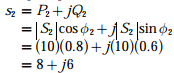
Again, the delivered power to load Z2 as
|s1|= 10 kVA
cos ϕ2 = 0.8, lagging
So, we obtain the complex power delivered to load Z2 as
Hence, the total complex power delivered by the source is
s1 + s2 = (10 – j7.5) + (8
+ j6)
= (18 - j1.5) kVA
Q3. A bulb in a staircase has two switches, one switch being at the ground floor and the other one at the first floor. The bulb can be turned ON and also can be turned OFF by any one of the switches irrespective of the state of the other switch. The logic of switching of the bulb resembles
Answer : Option C
Explaination / Solution:
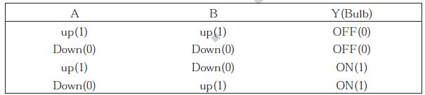

Let A denotes the position of switch at ground floor and B denotes the position of switch at upper floor. The switch can be either in up position or down position.Following are the truth table given for different combinations of A and B
When the switches A and B are both up or both down, output will be zero (i.e.Bulb will be OFF). Any of the switch changes its position leads to the ON state of bulb. Hence, from the truth table, we get
i.e., the XOR gate
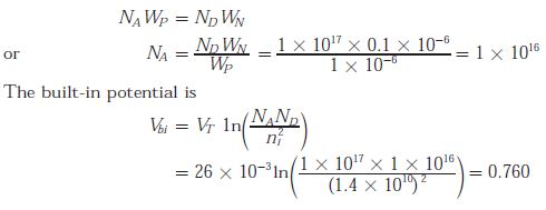
Q4. The built-in potential of the junction
Answer : Option B
Explaination / Solution:
We know that
Q5.
For 8085 microprocessor, the following program is executed.
MVI A, 05H;
MVI B, 05H;
PTR: ADD B;
DCR B;
JNZ PTR;
ADI 03H;
HLT;
At the end of program, accumulator contains
Answer : Option A
Explaination / Solution:
The program is being executed as follows
MVI A, 0.5H; A = 05H
MVI B, 0.5H; B = 05H
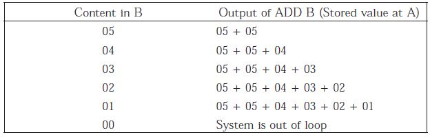
At the next instruction, a loop is being introduced in which for the instruction “DCR B” if the result is zero then it exits from loop so, the loop is executed five times as follows :
i.e., A = 05 + 05 + 04 + 03 + 02 + 01 = 144
At this stage, the 8085 microprocessor exits from the loop and reads the next instruction. i.e., the accumulator is being added to 03 H. Hence, we obtain A = A + 03 H = 14 + 03 = 17 H
Q6.
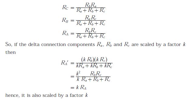
Consider a delta connection of resistors and its equivalent star connection as shown below. If all elements of the delta connection are scaled by a factor k, k > 0, the elements of the corresponding star equivalent will be scaled by a factor of
Answer : Option B
Explaination / Solution:
In the equivalent star connection, the resistance can be given as
Q7. The output Y in the circuit below is always ‘1’ when
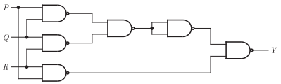
Answer : Option B
Explaination / Solution:
The given circuit is shown below:

If any two or more inputs are ‘1’ then output y will be 1.
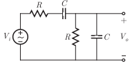
Q8. The circuit shown below is driven by a sinusoidal input Vi = Vpcos(t/RC). The
steady state output vo
Answer : Option A
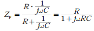
Explaination / Solution:
parallel combination of R and C equivalent impedance is
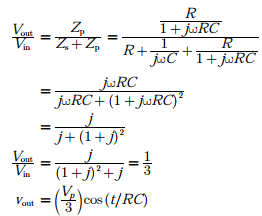
Transfer function can be written as
Q9. When the output Y in the circuit below is ‘1’, it implies that data has
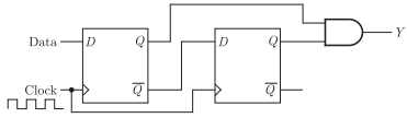
Answer : Option A
Explaination / Solution:
No Explaination.
Q10. The transfer function 
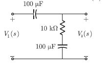
Answer : Option D
Explaination / Solution:
For the given capacitance,  in the circuit, we have the reactance.
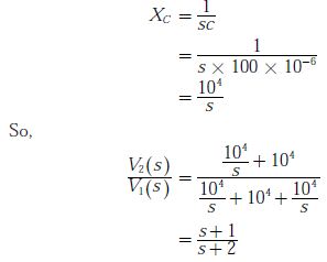
in the circuit, we have the reactance.