Electronic Science - Online Test
Q1. The depletion layer in the p-n junction region is caused by
Answer : Option B
Explaination / Solution:
In semiconductor physics, the depletion region, also called depletion layer, depletion zone, junction region, space charge region or space charge layer, is an insulating region within a conductive, doped semiconductor material where the mobile charge carriers have been diffused away, or have been forced away by an electric field. The only elements left in the depletion region are ionized donor or acceptor impurities.
Q2. 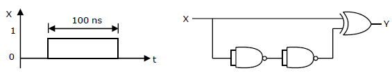
The TTL circuit shown in the figure is fed with the waveform X (also shown). All gates have equal propagation delay of 10ns. The output Y of the circuit is
Answer : Option A
Explaination / Solution:
No Explaination.
Q3. 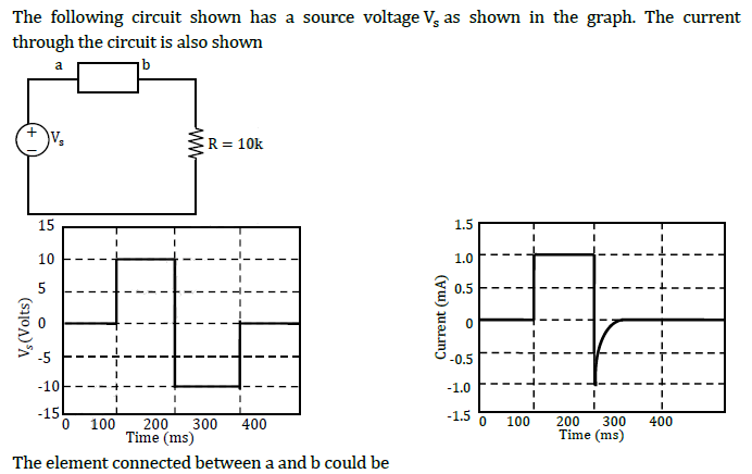
Answer : Option A
Explaination / Solution:
When diode is ON, i=1mA. When diode is OFF, i is zero after small reverse recovery time.
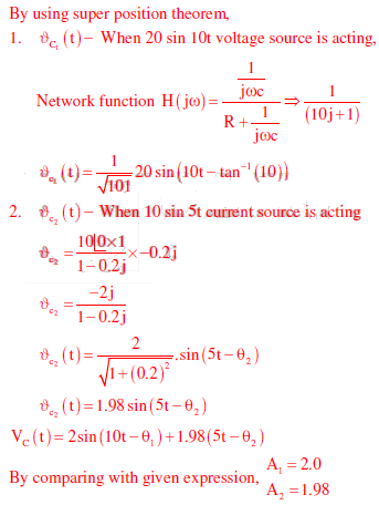
Q4. The voltage across the capacitor, as sown in the figure, is expressed as 
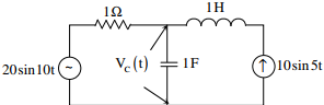
The value of A1 and A2 respectively, are
Answer : Option A
Explaination / Solution:
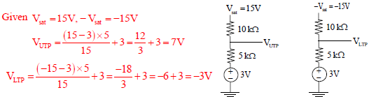
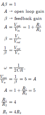
Q5. 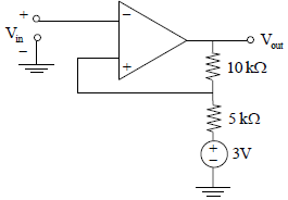
For the operational amplifier circuit shown, the output saturation voltages are ± 15V. The upper and lower threshold voltages for the circuit are, respectively.
Answer : Option B
Explaination / Solution:
Q6. 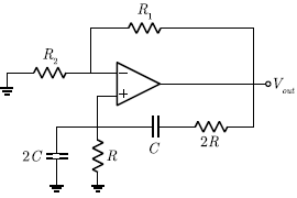
The circuit shown in the figure has an ideal opamp. The oscillation frequency and the condition to sustain the oscillations, respectively, are
Answer : Option D
Explaination / Solution:
By virtual ground property, we write
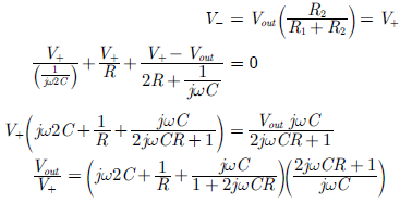
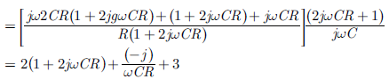
We equate imaginary part to zero, i.e.
The condition to sustain the oscillation is
Q7. The capacity of a pure capacitor is 1 farad. In DC circuit its effective resistance will be
Answer : Option D
Explaination / Solution:
Capacitor does not allow DC to pass through it. The effective capacitance or the capacitive reactance , where ω is the frequency of voltage source. Since DC current is a constant current, its frequency is zero. The capacitive reactance is therefore infinity.
Q8.
Two protons move parallel to each other with equal speeds 3 x 10⁵ ms-1. The ratio of magnetic and electric force between them is
Answer : Option B
Explaination / Solution:
The approximate ratio of the forces is equal to the ratio of their constants,and
Q9.
For the given circuit , with cell e m f = 10 V and internal resistance = , which of the following is correct?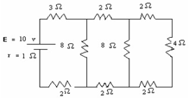
Answer : Option C
Explaination / Solution:
The circuit is reduced to find equivalent resistance as follows;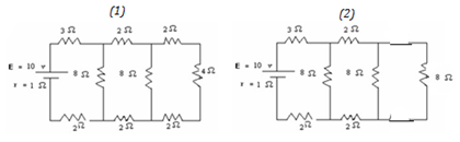
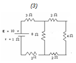
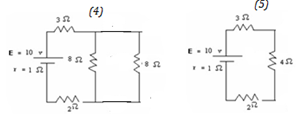
In (1), 2Ω, 4 Ω, and 2 Ω are in series. Their equivalent resistance is 8 Ω. In (2), the two 8 Ω resistors are in parallel and their equivalent resistance is 4 Ω. In (3) 2 Ω, 4 Ω, and 2 Ω are in series. Their equivalent resistance is 8 Ω which is in parallel with the 8 Ω resistance as shown in (4). The total resistance in the circuit
R= 3+4+2+1( internal resistance)=10 Ω. The current through the 3 Ω resistor
I = E/R = 10/10
I = 1A
Q10. Assuming one unpaired electron spin per atom, saturation magnetization in a long cylinder of iron is(n for iron is atoms/m3,Bohr magneton
Answer : Option C
Explaination / Solution:
No Explaination.
