Electronics Engineering - Online Test
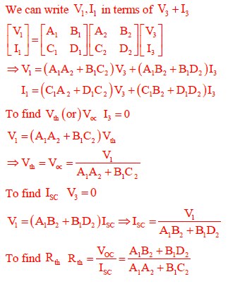
Q1. Two passive two-port networks are connected in cascade as shown in figure. A voltage source is
connected at port 1.
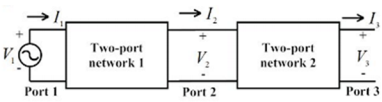
Given V1 = A1V2 + B1I2
I1 = C1V2 + D1I2
V2 = A2V3 + B2I3
A1 ,B1 ,C1 ,D1 ,A2 ,B2 ,C2 and D2 are the generalized circuit constants. If the Thevenin equivalent
circuit at port 3 consists of a voltage source VT and impedance ZT connected in series, then
Answer : Option D
Explaination / Solution:
Q2. 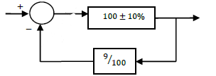
As shown in the figure, a negative feedback system has an amplifier of gain 100 with ±10% tolerance in the forward path, and an attenuator of value 9/100 in the feedback path. The overall system gain is approximately:
Answer : Option A
Explaination / Solution:
No Explaination.
Q3. x(t)is a positive rectangular pulse from t = −1 to t = +1 with unit height as shown in the figure. The value of  { where X(ω) is the Fourier transform of x(t)} is
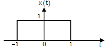
{ where X(ω) is the Fourier transform of x(t)} is
Answer : Option D
Explaination / Solution:
No Explaination.
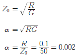
Q4. A transmission line has a characteristic impedance of 50 Ω and a resistance of 0.1Ω/m . If the line is distortion less, the attenuation constant(in Np/m) is
Answer : Option D
Explaination / Solution:
For distortion less transmission line characteristics impedance
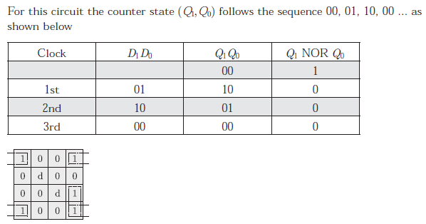
Q5. For the circuit shown, the counter state (Q1Q0) follows the sequence
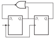
Answer : Option A
Explaination / Solution:
Q6. In the circuit below, the diode is ideal. The voltage V is given by
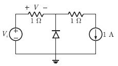
Answer : Option A
Explaination / Solution:
Let diode be OFF. In this case 1 A current will flow in resistor and voltage across resistor will be V = 1.V
Diode is off, it must be in reverse biased, therefore
Vi- 1 > 0 " Vi > 1
Thus for Vi > 1 diode is off and V = 1V
Option (B) and (C) doesn’t satisfy this condition.
Let Vi < 1. In this case diode will be on and voltage across diode will be zero and
V = Vi
Thus V = min(Vi,1)
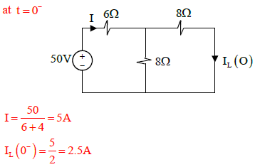
Q7. The switch in the figure below was closed for a long time. It is opened at t = 0. The current in
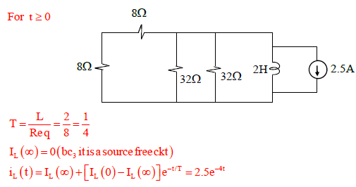
the inductor of 2 H for
t ≥ 0 is
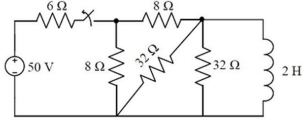
Answer : Option A
Explaination / Solution:
Q8. For the system 2/(s+1), the approximate time taken for a step response to reach 98% of its final value is
Answer : Option C
Explaination / Solution:
No Explaination.
Q9. 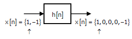
Given the finite length input x[n] and the corresponding finite length output y[n] of an LTI system as shown below, the impulse response h[n] of the system is
Answer : Option C
Explaination / Solution:
No Explaination.
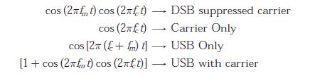
Q10.
For a message signal 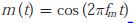 and carrier of frequency fc which of thefollowing represents a single side-band (SSB) signal ?
Answer : Option C
Explaination / Solution: