Electronics Engineering - Online Test
Q1. Two systems with impulse responses h1(t) and h2(t) are connected in cascade.
Then the overall impulse response of the cascaded system is given by
Answer : Option C
Explaination / Solution:
No Explaination.
Q2. The Voltage Source Inverter (VSI) shown in the figure below is switched to provide a 50 Hz, square-wave ac output voltage (v0) across an R-L load. Reference polarity of v0 and reference direction of the output current i0 are indicated in the figure. It is given that R = 3 Ω, L = 9.55 mH.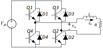
Appropriate transition i.e., Zero Voltage Switching (ZVS) / Zero Current Switching (ZCS) of the IGBTs during turn-on / turn-off is
Answer : Option D
Explaination / Solution:
No Explaination.
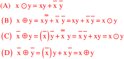
Q3. Which one of the following expressions does NOT represent exclusive NOR of x and y?
Answer : Option D
Explaination / Solution:
Q4. The following circuit has R = 10kΩ, C = 10μF . The input voltage is a sinusoid at 50Hz with an
rms value of 10V. Under ideal conditions, the current is from the source is
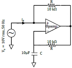
Answer : Option D
Explaination / Solution:
No Explaination.
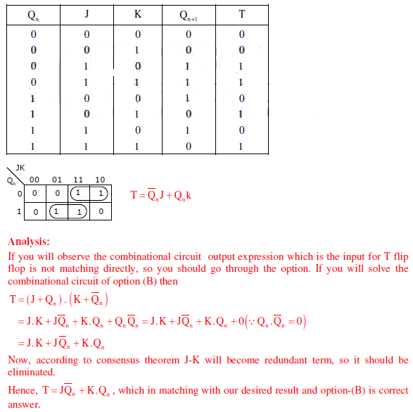
Q5. A JK flip flop can be implemented by T flip-flops. Identify the correct implementation.
Answer : Option B
Explaination / Solution:
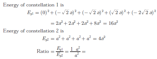
Q6. Two 4-array signal constellations are shown. It is given that φ1 and φ2 constitute
an orthonormal basis for the two constellation. Assume that the four symbols
in both the constellations are equiprobable. Let N0/2 denote the power spectral
density of white Gaussian noise.
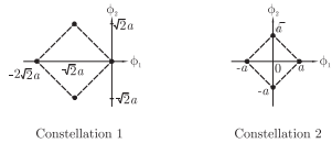
The if ratio or the average energy of Constellation 1 to the average energy of
Constellation 2 is
Answer : Option B
Explaination / Solution:
Q7. 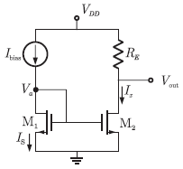
For the circuit shown in the following figure, transistor M1 and M2 are identical NMOS transistors. Assume the M2 is in saturation and the output is unloaded.
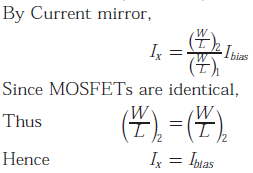
The current Ix is related to Ibias as
Answer : Option B
Explaination / Solution:
Q8. 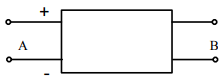
With 10 V dc connected at port A in the linear nonreciprocal two-port network shown below, the following were observed:
(i) 1Ω connected at port B draws a current of 3 A
(ii) 2.5Ω W connected at port B draws a current of 2 A
With 10 V dc connected at port A, the current drawn by 7 Ω connected at port B is
Answer : Option C
Explaination / Solution:
No Explaination.
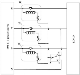
Q9. The load shown in the figure is supplied by a 400 V (line to line) 3-phase source (RYB
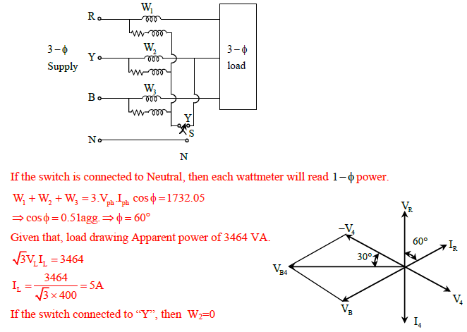
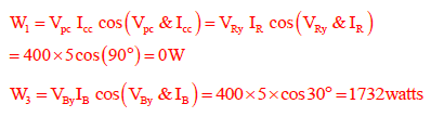
sequence). The load is balanced and inductive, drawing 3464 VA. When the switch S is in
position N, the three watt-meters W1, W2 and W3 read 577.35 W each. If the switch is moved to
position Y, the readings of the watt-meters in watts will be
Answer : Option D
Explaination / Solution:
Q10. Which one of the following statements is NOT TRUE for a continuous time causal and stable LTI system?
Answer : Option C
Explaination / Solution:
No Explaination.
