Electronic Science - Online Test
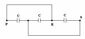
Q1. Three capacitors, each of capacitance C = 3 mF, are connected as shown in the figure. The equivalent capacitance between points P and S is
Answer : Option A
Explaination / Solution:
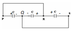
If P is at positive potential, then Q is at negative potential and R is at positive potential. The system therefore reduces to 3 capacitors in parallel. C= 9μF
If P is at positive potential, then Q is at negative potential and R is at positive potential. The system therefore reduces to 3 capacitors in parallel. C= 9μF
Q2. For a BJT the common base current gain α = 0.98 and the collector base
junction reverse bias saturation current ICO = 0.6 μA. This BJT is connected in
the common emitter mode and operated in the active region with a base drive
current IB = 204 A. The collector current IC for this mode of operation is
Answer : Option D
Explaination / Solution:
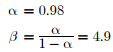
In active region, for common emitter amplifier,
Substituting ICO = 0.6 μA and IB = 204 μA in above eq we have,
IC = 1.01 mA
Q3. In a microprocessor, the service routine for a certain interrupt starts from a fixed location of memory which cannot be externally set, but the interrupt can be delayed or rejected Such an interrupt is
Answer : Option D
Explaination / Solution:
Vectored interrupts : Vectored interrupts are those interrupts in which program control transferred to a fixed memory location.
Maskable interrupts : Maskable interrupts are those interrupts which can be rejected or delayed by microprocessor if it is performing some critical task.
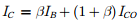
Q4. The Thevenin equivalent impedance Zth between the nodes P and Q in the
following circuit is
Answer : Option A
Explaination / Solution:
Killing all current source and voltage sources we have,
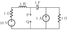
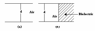
Q5. A parallel plate air filled capacitor shown in the Fig. (a) has a capacitance of 2 . When it is half filled with a dielectric of dielectric constant k = 3 as shown in Fig. (b), its capacitance becomes
Answer : Option D
Explaination / Solution:
The capacitance of the first capacitorThe second capacitor is considered to be made of two capacitors C1( air filled) and C2( dielectric) connected in series.
The equivalent capacitance
The equivalent capacitance
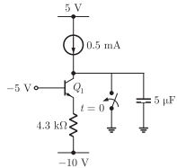
Q6. For the BJT QL in the circuit shown below,  The
switch is initially closed. At time t = 0, the switch is opened. The time t at
which Q1 leaves the active region is
The
switch is initially closed. At time t = 0, the switch is opened. The time t at
which Q1 leaves the active region is
The
switch is initially closed. At time t = 0, the switch is opened. The time t at
which Q1 leaves the active region is
Answer : Option C
Explaination / Solution:
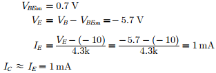
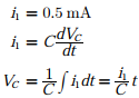
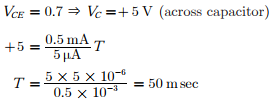
Applying KCL at collector
with time, the capacitor charges and voltage across collector changes from 0
towards negative.
Q7. 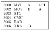
For the 8085 assembly language program given below, the content of the accumulator after the execution of the program is
Answer : Option C
Explaination / Solution:
By executing instruction one by one

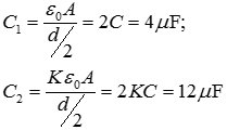
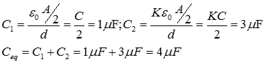
Q8. A parallel plate air filled capacitor shown in Fig. (a) has a capacitance of 2 . When it is half filled with a dielectric of dielectric constant k= 3 as shown in Fig. (b), its capacitance becomes
Answer : Option B
Explaination / Solution:
The capacitance of the first capacitor The second capacitor is considered to be made of two capacitors ( air filled) and ( dielectric) connected in parallel.
Q9. 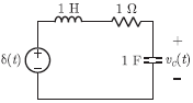
The following series RLC circuit with zero conditions is excited by a unit impulse functions 𝛿(t).
For t > 0, the output voltage vc(t) is
Answer : Option D
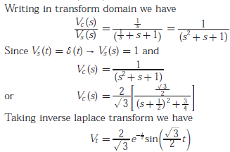
Explaination / Solution:
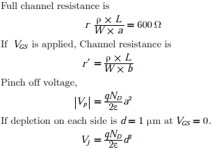
Q10. The channel resistance of an N-channel JFET shown in the figure below is 600Ω when the full channel thickness (tch) of 10μm is available for conduction. The
built-in voltage of the gate P+ N junction (Vbi) is -1 V. When the gate to source
voltage (VGS) is 0 V, the channel is depleted by 1 μm on each side due to the built
in voltage and hence the thickness available for conduction is only 8 μm
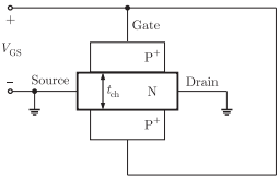
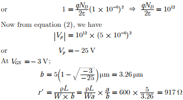
The channel resistance when VGS = -3 V is
Answer : Option B
Explaination / Solution: