Electronics Engineering - Online Test
Q1. For the transfer function G(j𝜔) = 5 + j𝜔, the corresponding Nyquist plot for positive frequency has the form
Answer : Option A
Explaination / Solution:
G(j𝜔) = 5 + j𝜔
Here σ = 5. Thus G(j𝜔) is a straight line parallel to j𝜔 axis
Q2. The block diagram of a system with one input it and two outputs y1 and y2 is
given below
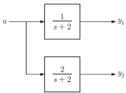
A state space model of the above system in terms of the state vector  and the
output vector
and the
output vector  is.
is.
is.
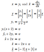
Answer : Option B
Explaination / Solution:
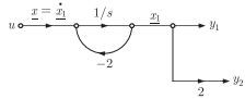
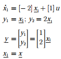
Drawing SFG as shown below
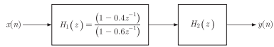
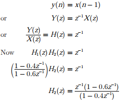
Q3. Two systems H1(Z) and H2(Z) are connected in cascade as shown below. The
overall output y(n) is the same as the input x(n) with a one unit delay. The
transfer function of the second system H2(Z)is
Answer : Option B
Explaination / Solution:
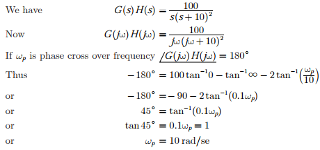
Q4. The input-output transfer function of a plant 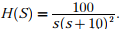 The plant is
placed in a unity negative feedback configuration as shown in the figure below.
The plant is
placed in a unity negative feedback configuration as shown in the figure below. 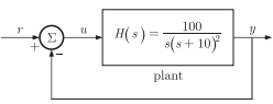
The plant is
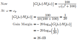
placed in a unity negative feedback configuration as shown in the figure below. The gain margin of the system under closed loop unity negative feedback is
Answer : Option C
Explaination / Solution:
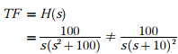
Q5. The input-output transfer function of a plant The plant is placed in a unity negative feedback configuration as shown in the figure below.
The plant is placed in a unity negative feedback configuration as shown in the figure below. The signal flow graph that DOES NOT model the plant transfer function H(S) is
Answer : Option D
Explaination / Solution:
Q6. Consider the sequence x[n] = anu[n] + bnu[n], where u[n] denotes the unit-step sequence and 0 < |a| < |b| < 1. The region of convergence (ROC) of the z-transform of x[n] is
Answer : Option B
Explaination / Solution:
No Explaination.
Q7. A closed-loop control system is stable if the Nyquist plot of the corresponding open-loop transfer function
Answer : Option A
Explaination / Solution:
No Explaination.
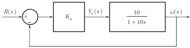
Q8. The open-loop transfer function of a dc motor is given a 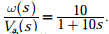 When connected in feedback as shown below, the approximate value of Ka that
will reduce the time constant of the closed loop system by one hundred times as
compared to that of the open-loop system is
When connected in feedback as shown below, the approximate value of Ka that
will reduce the time constant of the closed loop system by one hundred times as
compared to that of the open-loop system is
When connected in feedback as shown below, the approximate value of Ka that
will reduce the time constant of the closed loop system by one hundred times as
compared to that of the open-loop system is
Answer : Option C
Explaination / Solution:
No Explaination.
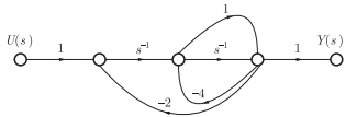
Q9. The signal flow graph for a system is given below. The transfer function Y(s)/U(s) for this system is
Answer : Option A
Explaination / Solution:
No Explaination.
