Electronics Engineering - Online Test
Q1. In an 8085 system, a PUSH operation requires more clock cycles than a POP operation. Which one of the following options is the correct reason for this?
Answer : Option C
Explaination / Solution:
In push operation 3 cycles involved: 6T+3T+3T = 127
POP operation 3 cycle involved: 4T+3T+3T = 107
So in the opcode fetch cycle 2T states are extra in case of push compared to POP and this is needed to decrement the SP.
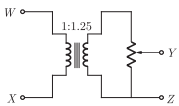
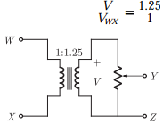
Q2. The following arrangement consists of an ideal transformer and an attenuator
which attenuates by a factor of 0.8. An ac voltage VWXI = 100 V is applied
across WX to get an open circuit voltage VYZ1 across YZ. Next, an ac voltage VYZ2 = 100 V is applied across YZ to get an open circuit voltage VWX2 across
WX. Then, VYZI/VWX1, VWX2/VYZ2 are respectively.
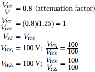
Answer : Option C
Explaination / Solution:
Q3.
Which one of the following statements is NOT TRUE for a continuous time causal and stable LTI system?
Answer : Option C
Explaination / Solution:
For a system to be casual, the R.O.C of system transfer function H(s) h which is rational should be in the right half plane and to the right of the right most pole.
For the stability of LTI system. All poles of the system should lie in the left half of S -plane and no repeated pole should be on imaginary axis. Hence,
options (A), (B), (D) satisfies an LTI system stability and causality both.
But, Option (C) is not true for the stable system as, ƖsƖ =1 have one pole in right hand plane also.
Q4. The DFT of a vector [a b c d] is the vector [α β γ δ]. Consider the product 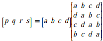
The DFT of the vector [p q r s] is a scaled version of
Answer : Option A
Explaination / Solution:
No Explaination.
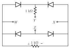
Q5. A voltage 1000 sin𝜔t Volts is applied across YZ . Assuming ideal diodes, the
voltage measured across WX in Volts, is
Answer : Option D
Explaination / Solution:
No Explaination.
Q6. An analog signal is band-limited to 4 kHz, sampled at the Nyquist rate and the samples are quantized into 4 levels. The quantized levels are assumed to be independent and equally probable. If we transmit two quantized samples per second, the information rate is ________ bits / second.
Answer : Option D
Explaination / Solution:
Quantized 4 level require 2 bit representation i.e. for one sample 2 bit are required. Since 2 sample per second are transmitted we require 4 bit to be transmitted per second.
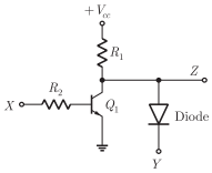
Q7. In the circuit shown below, Q1 has negligible collector-to-emitter saturation voltage and the diode drops negligible voltage across it under forward bias. If Vcc is +5 V, X and Y are digital signals with 0 V as logic 0 and Vcc as logic 1,
then the Boolean expression for Z is
Answer : Option B
Explaination / Solution:
No Explaination.
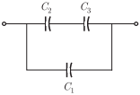
Q8. Three capacitors C1, C2 and C3 whose values are 10 μF , 5 μF , and 2 μF respectively, have breakdown voltages of 10 V, 5 V and 2 V respectively. For the
interconnection shown below, the maximum safe voltage in Volts that can be
applied across the combination, and the corresponding total charge in μC stored
in the effective capacitance across the terminals are respectively
Answer : Option C
Explaination / Solution:
No Explaination.
Q9. The root locus plot for a system is given below. The open loop transfer function
corresponding to this plot is given by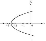
Answer : Option B
Explaination / Solution:
For given plot root locus exists from -3 to ∞, So there must be odd number of
poles and zeros. There is a double pole at s = - 3
Now poles = 0, -2, -3, -3
zeros = - 1
Thus transfer function 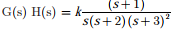
Q10. There are four chips each of 1024 bytes connected to a 16 bit address bus as
shown in the figure below, RAMs 1, 2, 3 and 4 respectively are mappped to
addresses
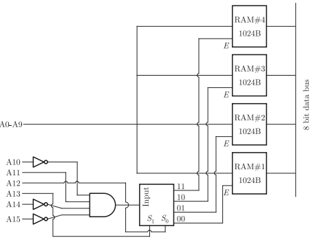
Answer : Option D
Explaination / Solution:
No Explaination.
