Electronics Engineering - Online Test
Q1. 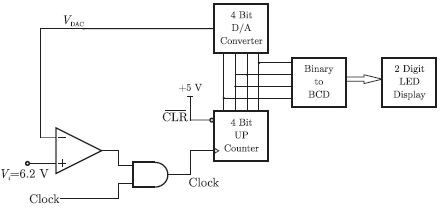
In the following circuit, the comparators output is logic “1” if V1 > V2 and is logic "0" otherwise. The D/A conversion is done as per the relation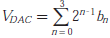 Volts, where b3 (MSB), b1,b2 and b0 (LSB) are the counter outputs. The counter starts from the clear state.
Volts, where b3 (MSB), b1,b2 and b0 (LSB) are the counter outputs. The counter starts from the clear state.The magnitude of the error between VDAC and Vin at steady state in volts is
Answer : Option B
Explaination / Solution:
No Explaination.
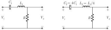
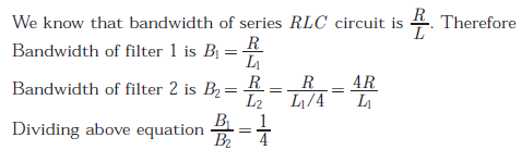
Q2. Two series resonant filters are as shown in the figure. Let the 3-dB bandwidth
of Filter 1 be B1 and that of Filter 2 be B2. the value B1/B2 is
Answer : Option D
Explaination / Solution:
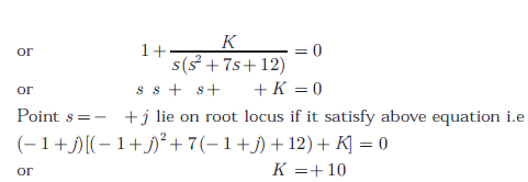
Q3. A unity feedback control system has an open-loop transfer function 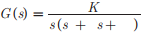 . The gain K for which s = +j will lie on the root locus of this system is
. The gain K for which s = +j will lie on the root locus of this system is
Answer : Option D
Explaination / Solution:
Q4. A sinusoidal signal of 2 kHz frequency is applied to a delta modulator. The sampling rate and step-size Δ of the delta modulator are 20,000 samples per second and 0.1 V, respectively. To prevent slope overload, the maximum amplitude of the sinusoidal signal (in Volts) is
Answer : Option A
Explaination / Solution:
For preventing slope overload, we should have
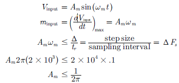
(slope of m(t) ≤ (slope of sampling)
For sinusoidal signal, if
Q5.
Consider a linear system whose state space representation is x(t) = Ax(t). If the initial state vector of the system is  then the system response is
 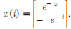 If the itial state vector of the system changes to the system response becomes
then the system response is If the itial state vector of the system changes to the system response becomes The system matrix A is
Answer : Option D
Explaination / Solution:
No Explaination.
Q6. In the circuit shown below, capacitors C1 and C2 are very large and are shorts
at the input frequency. vi is a small signal input. The gain magnitude  at 10
M rad/s is
at 10
M rad/s is
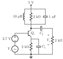
Answer : Option A
Explaination / Solution:
For the parallel RLC circuit resonance frequency is,
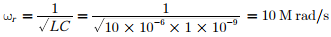
 which is maximum
Thus given frequency is resonance frequency and parallel RLC circuit has
maximum impedance at resonance frequency
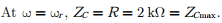
Gain of the amplifier is  where ZC is impedance of parallel RLC
circuit.
where ZC is impedance of parallel RLC
circuit.
where ZC is impedance of parallel RLC
circuit.Hence at this frequency (ωr), gain is
which is maximumTherefore gain is maximum at ωr = 10 /sec M rad .
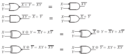
Q7. Match the logic gates in Column A with their equivalents in Column B
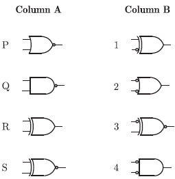
Answer : Option D
Explaination / Solution:
Q8. 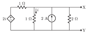
For the circuit shown in the figure, the Thevenin voltage and resistance looking into X − Y are
Answer : Option D
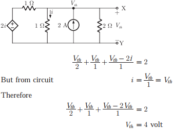
Explaination / Solution:
Here Vth is voltage across node also. Applying nodal analysis we get
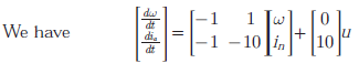
Q9. The state space representation of a separately excited DC servo motor dynamics
is given as
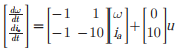
where ω is the speed of the motor, ia is the armature current and u is the
armature voltage. The transfer function ω(s)/U(s) of the motor is
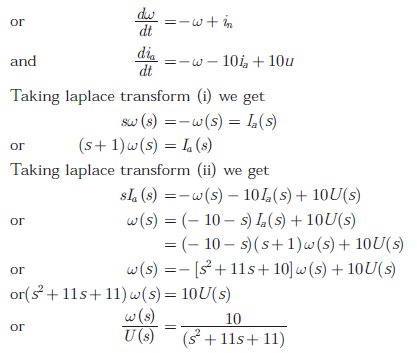
Answer : Option D
Explaination / Solution:
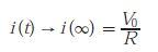
Q10. The time domain behavior of an RL circuit is represented by 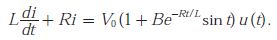 For an initial current of
For an initial current ofFor an initial current of  the steady state value of the current is given by
the steady state value of the current is given by
Answer : Option A
Explaination / Solution:
Steady state all transient effect die out and inductor act as short circuits and forced response acts only. It doesn’t depend on initial current state. From the given time domain behavior we get that circuit has only R and L in series with v0 Thus at steady state