Electronics Engineering - Online Test
Q1. 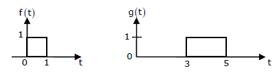
Given f(t) and g(t) as shown below:
g(t) can be expressed as
Answer : Option D
Explaination / Solution:
No Explaination.
Q2. X(t) is a stationary process with the power spectral density Sx(f)>0, for all f . The process is passed through a system shown below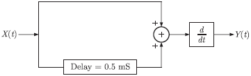
Let Sy (f ) be the power spectral density of Y(t). Which one of the following statements is correct
Answer : Option D
Explaination / Solution:
Q3. An 8085 assembly language program is given below.
Line 1: MVI A, B5H
2: MVI B, OEH
3: XRI 69H
4: ADD B
5: ANI 9BH
6: CPI 9FH
7: STA 3010H
8: HLT
After execution of line 7 of the program, the status of the CY and Z flags will be
Answer : Option C
Explaination / Solution:
No Explaination.
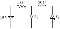
Q4. In the figure, assume that the forward voltage drops of the PN diode D1 and
Schottky diode D2 are 0 7. V and 0 3. V, respectively. If ON denotes conducting
state of the diode and OFF denotes non-conducting state of the diode, then in
the circuit,
Answer : Option D
Explaination / Solution:
Alternatively, we can solve the problem by considering the current through two
diodes. Here, the correct case is only considered. 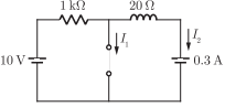
Case : Diode D1 is OFF, D2 is ON. For this case. The equivalent circuit is
From the circuit, we have
I1 = 0
I2 = 10 - 2.3/1.02
= 9.7/1.02
= 9.5 mA
Since, the current I2 is positive, So our assumption is correct.
Q5. As shown in the figure, a 1Ω resistance is connected across a source that has a load line v + i =
100. The current through the resistance is
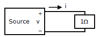
Answer : Option B
Explaination / Solution:
No Explaination.
Q6. Given f(t) and g(t) as shown below:

The Laplace transform of g(t) is
Answer : Option C
Explaination / Solution:
No Explaination.
Q7. The measurement system shown figure uses three sub-system in cascade whose gains are
specified as G1, G2 and 1/G3. The relative small errors associated with each respective
subsystem G1, G2 and G3 are ε1 + ε2 and ε3. The error associated with the output is

Answer : Option C
Explaination / Solution:
No Explaination.
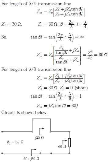
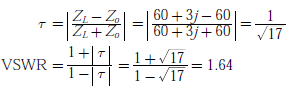
Q8. 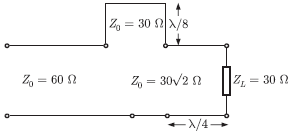
In the circuit shown, all the transmission line sections are lossless. The Voltage Standing Wave Ration(VSWR) on the 60 Ω line is
Answer : Option B
Explaination / Solution:
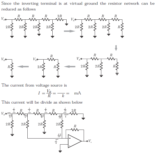
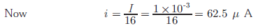
Q9. In the Digital-to-Analog converter circuit shown in the figure below, VR = 1V and R = 1kΩ
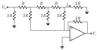
The current i is
Answer : Option B
Explaination / Solution:
Q10. If fixed positive charges are present in the gate oxide of an n-channel enhancement type MOSFET, it will lead to
Answer : Option A
Explaination / Solution:
If fixed positive charges are present is the gate oxide of an n-channel enhancement type MOSFET, it will lead to a decrease in the threshold voltage.
