Electronics Engineering - Online Test
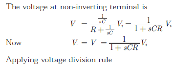
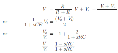
Q1. Consider the Op-Amp circuit shown in the figure. 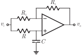
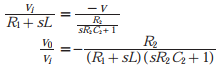
The transfer function V(s) Vi(s)
Answer : Option A
Explaination / Solution:
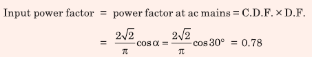
Q2. A single-phase thyristor-bridge rectifier is fed from a 230 V, 50 Hz, single-phase AC mains. If it is delivering a constant DC current of 10 A, at firing angle of 30º, then value of the power factor at AC mains is
Answer : Option C
Explaination / Solution:
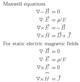
Q3. For static electric and magnetic fields in an inhomogeneous source-free medium, which of the following represents the correct form of Maxwell’s equations ?
Answer : Option D
Explaination / Solution:
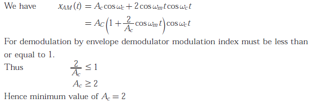
Q4. Consider the amplitude modulated (AM) signal 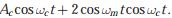 For demodulating the signal using envelope detector, the minimum value of Ac should be
For demodulating the signal using envelope detector, the minimum value of Ac should be
Answer : Option A
Explaination / Solution:
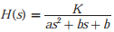
Q5. 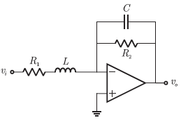
The OPAMP circuit shown above represents a
Answer : Option B
Explaination / Solution:
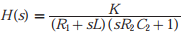
and from this equation it may be easily seen that this is the standard form of
T.F. of low pass filter
and form this equation it may be easily seen that this is the standard form of
T.F. of low pass filter
Q6. A bulb in a staircase has two switches, one switch being at the ground floor and the other one at the first floor. The bulb can be turned ON and also can be turned OFF by any one of the switches irrespective of the state of the other switch. The logic of switching of the bulb resembles
Answer : Option C
Explaination / Solution:
No Explaination.
Q7. 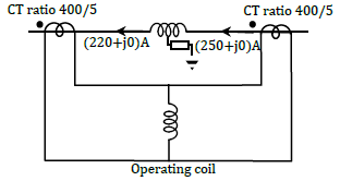
Consider a stator winding of an alternator with an internal high-resistance ground fault. The currents under the fault condition are as shown in the figure. The winding is protected using a differential current scheme with current transformers of ratio 400/5 A as shown. The current through the operating coil is
Answer : Option C
Explaination / Solution:
No Explaination.
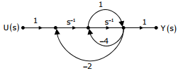
Q8. The signal flow graph for a system is given below. The Transfer function, Y(s)/U(s) for the system is
Answer : Option A
Explaination / Solution:
No Explaination.
Q9. The state variable formulation of a system is given as 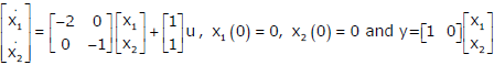
The system is
Answer : Option A
Explaination / Solution:
No Explaination.
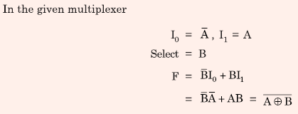
Q10. 
Consider the following circuit which uses a 2-to-1 multiplexer as shown in the figure below. The Boolean expression for output F in terms of A and B is
Answer : Option D
Explaination / Solution: