Electronics Engineering - Online Test
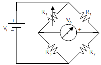
Q1. A strain gauge forms one arm of the bridge shown in the figure below and has a nominal resistance
without any load as Rs = 300 Ω. Other bridge resistances are R1 = R2 = R3 = 300 Ω. The maximum
permissible current through the strain gauge is 20 mA. During certain measurement when the
bridge is excited by maximum permissible voltage and the strain gauge resistance is increased by
1% over the nominal value, the output voltage V0 in mV is
Answer : Option C
Explaination / Solution:
No Explaination.
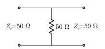
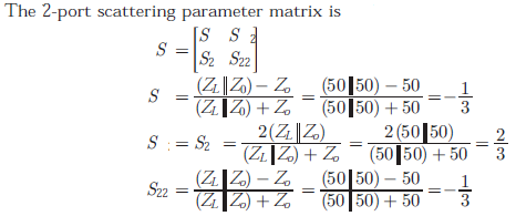
Q2. A load of 50 Ω is connected in shunt in a 2-wire transmission line of Z0 = 50Ω as shown in the figure. The 2-port scattering parameter matrix (s-matrix) of the
shunt element is
Answer : Option C
Explaination / Solution:
Q3. Which of the following is true?
Answer : Option A
Explaination / Solution:
Trivalent impurities are used for making p - type semiconductors. So, Silicon wafer heavily doped with boron is a p+ substrate.
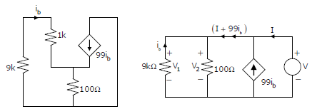
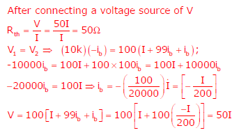
Q4. 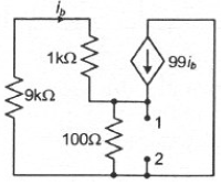
The impedance looking into nodes 1 and 2 in the given circuit is
Answer : Option A
Explaination / Solution:
Q5. 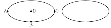
Two electrodes, whose cross-sectional view is shown in the figure below, are at the same potential. The maximum electric field will be at the point
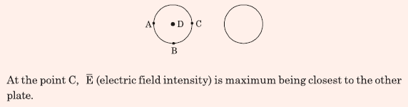
Answer : Option C
Explaination / Solution:
Q6. 
The transfer function of a compensator is given as
Gc(s) is a lead compensator if
Answer : Option A
Explaination / Solution:
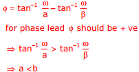
both option (A) and (C) satisfier but option (C) will pot polar and zero as RHS of s-plane thus not possible option (A) is right
Q7. 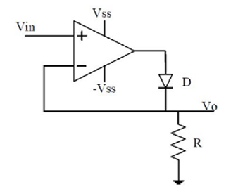
The approximate transfer characteristic for the circuit shown below with an ideal operational amplifier and diode will be
Answer : Option A
Explaination / Solution:
No Explaination.
Q8. A band-limited signal with a maximum frequency of 5 kHz is to be sampled. According to the sampling theorem, the sampling frequency in kHz which is not valid is
Answer : Option A
Explaination / Solution:
No Explaination.
Q9. The truth table
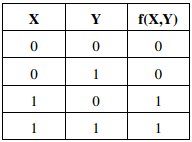
represents the Boolean function
Answer : Option A
Explaination / Solution:
XY'+ XY = X(Y'+ Y) = X
Q10. 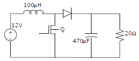
In the figure shown below, the chopper feeds a resistive load from a battery source. MOSFET Q is switched at 250 kHz, with a duty ratio of 0.4. All elements of the circuit are assumed to be ideal
The Peak to Peak source current ripple in amps is
Answer : Option C
Explaination / Solution:
No Explaination.
