Electrical Engineering - Online Test
Q1. For the circuit shown in the figure, the voltage and current expressions are 
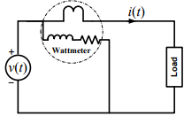
The average power measured by the Wattmeter is
Answer : Option C
Explaination / Solution:
Q2. The typical ratio of latching current to holding current in a 20 A thyristor is
Answer : Option B
Explaination / Solution:
No Explaination.
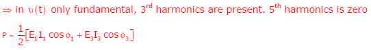
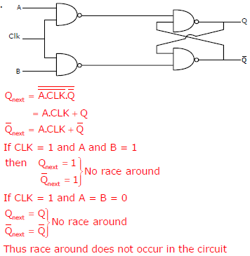
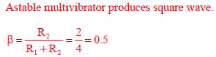
Q3. Consider the given circuit.
In this circuit, the race around
Answer : Option A
Explaination / Solution:
Q4. Match the following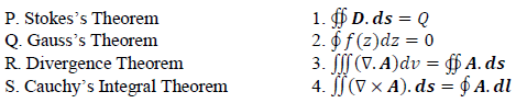
Answer : Option B
Explaination / Solution:
No Explaination.
Q5. 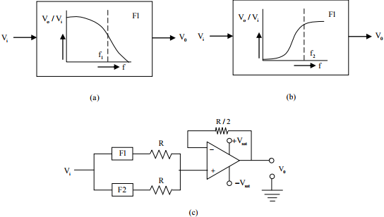
The filters F1 and F2 having characteristics as shown in Figures (a) and (b) are connected as shown in Figure (c).
The cut-off frequencies of F1 and F2 are f1 and f2 respectively. If f1 < f2 the resultant
circuit exhibits the characteristics of a
Answer : Option B
Explaination / Solution:
No Explaination.
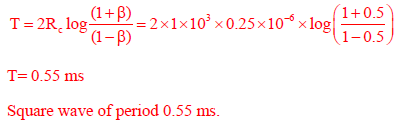
Q6. The saturation voltage of the ideal op-amp shown below is ±10V. The output voltage v0 of
the following circuit in the steady-state is
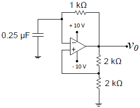
Answer : Option A
Explaination / Solution:
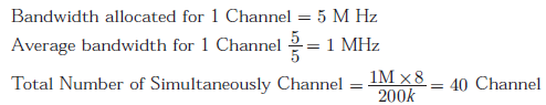
Q7. In a GSM system, 8 channels can co-exist in 200 kHz bandwidth using TDMA.
A GSM based cellular operator is allocated 5 MHz bandwidth. Assuming a
frequency reuse factor of 1/5, i.e. a five-cell repeat pattern, the maximum number
of simultaneous channels that can exist in one cell is
Answer : Option B
Explaination / Solution:
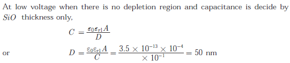
Q8. The figure shows the high-frequency capacitance - voltage characteristics of Metal/Sio2/silicon (MOS) capacitor having an area of 1 × 10⁻⁴ cm2. Assume that the permittivities (ε0εr) of silicon and Sio are 1 × 10-12 F/cm and 3.5 × 10⁻¹³ F/ cm respectively.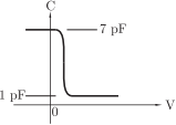
The gate oxide thickness in the MOS capacitor is
Answer : Option A
Explaination / Solution:
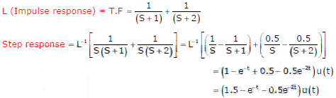
Q9. The response h(t) of a linear time invariant system to an impulse δ(t) , under
initially relaxed condition is  The response of this system for a
unit step input u(t) is
The response of this system for a
unit step input u(t) is
The response of this system for a
unit step input u(t) is
Answer : Option C
Explaination / Solution:
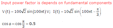
Q10. The input voltage given to a converter is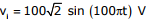

The current drawn by the converter is
The input power factor of the converter is
Answer : Option C
Explaination / Solution: