Electrical Engineering - Online Test
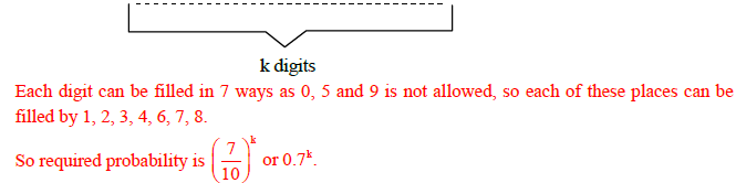
Q1. The probability that a k-digit number does NOT contain the digits 0.5, or 9 is
Answer : Option C
Explaination / Solution:
Q2. The L-C circuit shown in the figure has an inductance L = 1mH and a capacitance
C = 10µF. 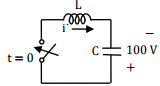
The initial current through the inductor is zero, while the initial capacitor voltage is 100 V. The switch is closed at t = 0. The current i through the circuit is:
Answer : Option D
Explaination / Solution:
No Explaination.
Q3. The unit-step response of a unity feedback system with open loop transfer function G(s)  is shown in the figure. The value of K is
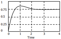
is shown in the figure. The value of K is
Answer : Option D
Explaination / Solution:
No Explaination.
Q4. Match the items in List-I with the items in List-II and select the correct answer using the codes given below the lists.
List I List II
a. Short Line 1. Ohm Relay
b. Medium Line 2. Reactance Relay
c. Long Line 3. Mho Relay
Answer : Option C
Explaination / Solution:
No Explaination.
Q5. Which one of the following statements about differential pulse code modulation (DPCM) is true?
Answer : Option D
Explaination / Solution:
DPCM Block diagram
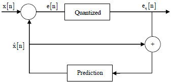
eq[n] is quantized e[n]
e[n] is difference of message signal sample with its prediction.
Q6. Three functions f(t), f2(t) and f3(t) which are zero outside the interval [0, T] are
shown in the figure. Which of the following statements is correct?
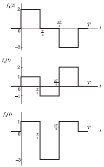
Answer : Option C
Explaination / Solution:
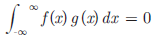
For two orthogonal signal f (x) and g(x)
i.e. common area between f x and g x is zero.
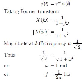
Q7. The 3-dB bandwidth of the low-pass signal e-t u(t), where u(t) is the unit step
function, is given by
Answer : Option A
Explaination / Solution:
Q8.
For small increase in VG beyond 1V, which of the following gives the correct description of the region of operation of each MOSFET
Answer : Option D
Explaination / Solution:
For small increase in VG beyond 1 V the n - channel MOSFET goes into saturation as VGS + ive and p - MOSFET is always in active region or triode region.
Q9. For the circuit shown in the following, I0 - I3 are inputs to the 4:1 multiplexers,
R(MSB) and S are control bits. 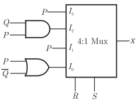
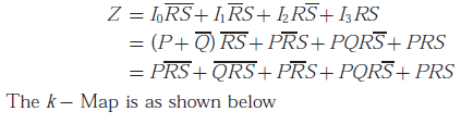
The output Z can be represented by
Answer : Option A
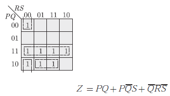
Explaination / Solution:
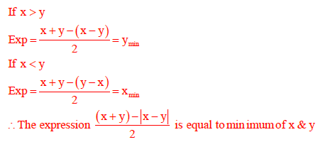
Q10. The expression ((x + Y) - |x - y|)/2 is equal to
Answer : Option B
Explaination / Solution: