Electrical Engineering - Online Test
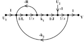
Q1. In the system whose signal flow graph is shown in the figure, U1(s) and U2(s) are inputs. The
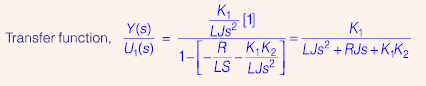
transfer function Y(s)/U1(s) is
Answer : Option A
Explaination / Solution:
Q2. At t = 0, the function f(t) = sint/t has
Answer : Option B
Explaination / Solution:
No Explaination.
Q3. If the scattering matrix [S ] of a two port network is 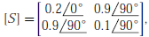 then the network is
then the network is
Answer : Option C
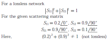
Explaination / Solution:
Q4. 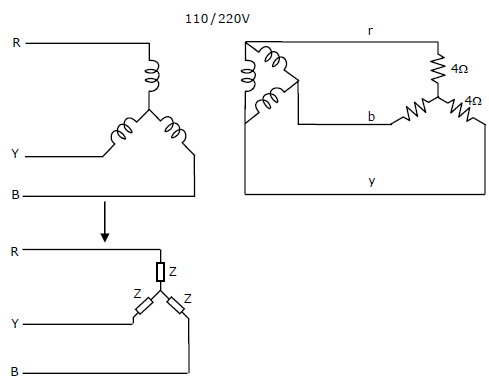
A balanced star-connected and purely resistive load is connected at the secondary of a stardelta transformer as shown in figure. The line-to-line voltage rating of the transformer is 110V/220V. Neglecting the non-idealities of the transformer, the impedance ‘Z’ of the equivalent star-connected load, referred to the primary side o the transformer, is:
Answer : Option D
Explaination / Solution:
No Explaination.
Q5. The following binary values were applied to the X and Y inputs of NAND latch
shown in the figure in the sequence indicated below : 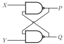
X = ,Y = X = ,Y = X = Y =
The corresponding stable P Q, output will be
Answer : Option C
Explaination / Solution:
No Explaination.
Q6. For the circuit with ideal diodes shown in the figure, the shape of the output (Vout) for the given sine wave input (Vin) will be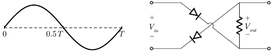
Answer : Option C
Explaination / Solution:
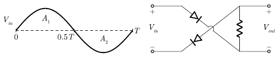
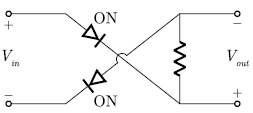
For positive half A1, we have
Vout = - Vin
For negative half A2, both diode will be OFF.
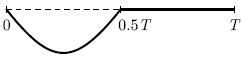
So, Vout = 0
Hence, the output is obtained as
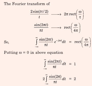
Q7. The value of the integral  is equal to
is equal to
Answer : Option D
Explaination / Solution:
Q8. Two passive two-port networks are connected in cascade as shown in figure. A voltage source is
connected at port 1.
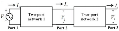
Given V1 = A1V2 + B1I2
I1 = C1V2 + D1I2
V2 = A2V3 + B2I3
A1 ,B1 ,C1 ,D1 ,A2 ,B2 ,C2 and D2 are the generalized circuit constants. If the Thevenin equivalent
circuit at port 3 consists of a voltage source VT and impedance ZT connected in series, then
Answer : Option D
Explaination / Solution:

Q9. 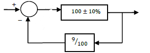
As shown in the figure, a negative feedback system has an amplifier of gain 100 with ±10% tolerance in the forward path, and an attenuator of value 9/100 in the feedback path. The overall system gain is approximately:
Answer : Option A
Explaination / Solution:
No Explaination.
Q10. x(t)is a positive rectangular pulse from t = −1 to t = +1 with unit height as shown in the figure. The value of  { where X(ω) is the Fourier transform of x(t)} is
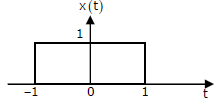
{ where X(ω) is the Fourier transform of x(t)} is
Answer : Option D
Explaination / Solution:
No Explaination.
