Electrical Engineering - Online Test
Q1. The period of the signal 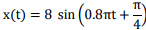 is
is
is
Answer : Option D
Explaination / Solution:
No Explaination.
Q2. The zero-sequence circuit of the three phase transformer shown in the figure is
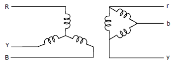
Answer : Option C
Explaination / Solution:
No Explaination.
Q3. Suppose that the modulating signal is 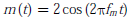 and the carrier signal is
 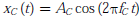 , which one of the following is a conventional AM signal without over-modulation
and the carrier signal is , which one of the following is a conventional AM signal without over-modulation
Answer : Option C
Explaination / Solution:
No Explaination.
Q4. 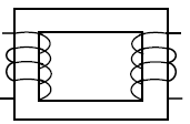
The single phase, 50Hz, iron core transformer in the circuit has both the vertical arms of cross sectional area 20cm2 and both the horizontal arms of cross sectional area 10cm2. If the two windings shown were wound instead on opposite horizontal arms, the mutual inductance will
Answer : Option A
Explaination / Solution:
No Explaination.
Q5. The current density in a medium is given by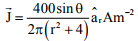 The total current and the average current density flowing through the portion of a spherical
surface r = 0.8 m,
The total current and the average current density flowing through the portion of a spherical
surface r = 0.8 m, 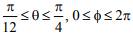 are given, respectively, by
The total current and the average current density flowing through the portion of a spherical
surface r = 0.8 m, are given, respectively, by
Answer : Option A
Explaination / Solution:
No Explaination.
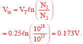
Q6. An n+ - n Silicon device is fabricated with uniform and non-degenerate donor doping concentrations of ND1 = 1 × 10¹⁸
cm-3 and ND2 = 1 × 10¹⁵
cm-3 corresponding to the n+ and n regions respectively. At the operational temperature T, assume complete impurity ionization, kT/q = 25 mV, and intrinsic carrier concentration to be ni = 1 × 1010 cm-3, What is the magnitude of the built-in potential of this device?
Answer : Option D
Explaination / Solution:
Q7. In the circuit shown below the op-amps are ideal. Then, Vout in Volts is
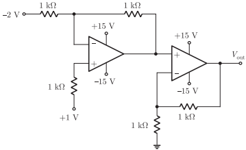
Answer : Option C
Explaination / Solution:
No Explaination.
Q8. The circuit diagram of a standard TTL NOT gate is shown in the figure. Vi = 25 V, the modes of operation of the transistors will be
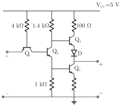
Answer : Option B
Explaination / Solution:
No Explaination.
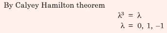
Q9. A 3 × 3 matrix P is such that, P3 = P. Then the eigenvalues of P are
Answer : Option D
Explaination / Solution:
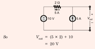
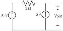
Q10. In the circuit shown below, the voltage and current sources are ideal. The voltage (Vout) across the
current source, in volts, is
Answer : Option D
Explaination / Solution: