Electrical Engineering - Online Test
Q1. A band-limited signal with a maximum frequency of 5 kHz is to be sampled. According to the sampling theorem, the sampling frequency in kHz which is not valid is
Answer : Option A
Explaination / Solution:
No Explaination.
Q2. The truth table
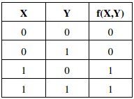
represents the Boolean function
Answer : Option A
Explaination / Solution:
XY'+ XY = X(Y'+ Y) = X
Q3. 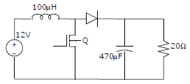
In the figure shown below, the chopper feeds a resistive load from a battery source. MOSFET Q is switched at 250 kHz, with a duty ratio of 0.4. All elements of the circuit are assumed to be ideal
The Peak to Peak source current ripple in amps is
Answer : Option C
Explaination / Solution:
No Explaination.
Q4. Which of the following is an invalid state in an 8-4-2-1. Binary Coded Decimal counter
Answer : Option D
Explaination / Solution:
In binary coded decimal (BCD) counter the valid states are from 0 to 9 only in binary system 0000 to 1001 only. So, 1100 in decimal it is 12 which is invalid state in BCD counter.
Q5. Match the following:
Instrument Type Used for
P. Permanent magnet moving coil 1. DC only
Q. Moving iron connected through current transformer 2. AC only
R. Rectifier 3.AC and DC
S. Electrodynamometer
Answer : Option C
Explaination / Solution:
No Explaination.
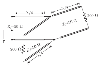
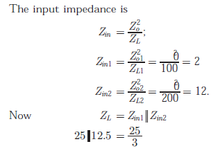
Q6. The parallel branches of a 2-wire transmission line re terminated in 100Ω and
200Ω resistors as shown in the figure. The characteristic impedance of the
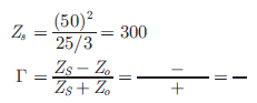
line is Z0 = Ω and each section has a length of λ/4. The voltage reflection
coefficient Γ at the input is
Answer : Option D
Explaination / Solution:
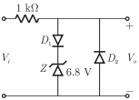
Q7. In the following limiter circuit, an input voltage Vi = 10 sin100πt is applied.
Assume that the diode drop is 0.7 V when it is forward biased. When it is
forward biased. The zener breakdown voltage is 6.8 V
The maximum and minimum values of the output voltage respectively are
Answer : Option C
Explaination / Solution:
No Explaination.
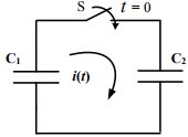
Q8. In the following figure, C1 and C2 are ideal capacitors. C1 has been charged to 12 V before the ideal
switch S is closed at t = 0. The current i(t) for all t is
Answer : Option D
Explaination / Solution:
Time constant = RC
In the given circuit, R = 0
Rise time = 0; hence capacitor charges instantaneously and the current can be represented as impulse function
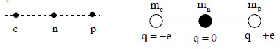
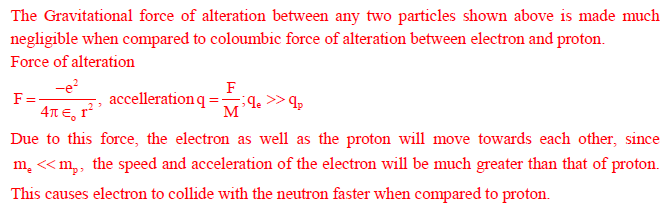
Q9. Consider an electron, a neutron and a proton initially at rest and placed along a straight line such that the neutron is exactly at the center of the line joining the electron and proton. At t=0, the particles are released but are constrained to move along the same straight line. Which of these will collide first?
Answer : Option D
Explaination / Solution:
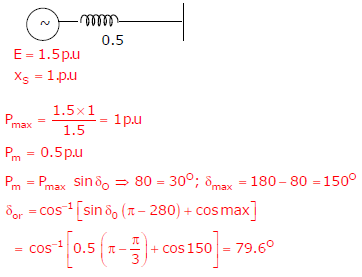
Q10. A cylindrical rotor generator delivers 0.5 pu power in the steady-state to an infinite bus through a
transmission line of reactance 0.5 pu. The generator no-load voltage is 1.5 pu and the infinite bus
voltage is 1 pu. The inertia constant of the generator is 5 MW-s/MVA and the generator reactance
is 1 pu. The critical clearing angle, in degrees, for a three-phase dead short circuit fault at the
generator terminal is
Answer : Option D
Explaination / Solution: