Electronics Engineering - Online Test
Q1. In the circuit shown, the power supplied by the voltage source is
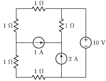
Answer : Option A
Explaination / Solution:
Applying nodal analysis
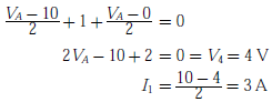
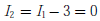
Current from voltage source is
Since current through voltage source is zero, therefore power delivered is zero.
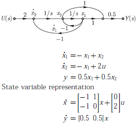
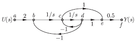
Q2. The signal flow graph of a system is shown below:

The state variable representation of the system can be
Answer : Option D
Explaination / Solution:
Q3. 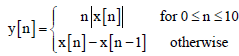
Consider a single input single output discrete-time system with x[n] as input and y[n] as output, where the two are related as
Which one of the following statements is true about the system?
Answer : Option A
Explaination / Solution:

For an input-output relation if the present output depends on present and past input values then the given system is “Causal”.
For the given relation,
For n ranging from 0 to 10 present output depends on present input only.
At all other points present output depends on present and past input values.
Thus the system is “Causal”.
Stability
If x[n] is bounded for the given finite range of n i.e. 0 ≤ n ≤ 10 y[n] is also bounded.
Similarly x[n] - x[n-1] is also bounded at all other values of n
Thus the system is “stable”.
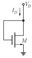
Q4. The small-signal resistance  in kW offered by the n-channel
MOSFET M shown in the figure below, at a bias point of VB = 2V is (device
data for M: device transconductance parameter
in kW offered by the n-channel
MOSFET M shown in the figure below, at a bias point of VB = 2V is (device
data for M: device transconductance parameter 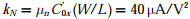 , threshold voltage VTN = 1V, and neglect body effect and channel length
modulation effects)
, threshold voltage VTN = 1V, and neglect body effect and channel length
modulation effects)
in kW offered by the n-channel
MOSFET M shown in the figure below, at a bias point of VB = 2V is (device
data for M: device transconductance parameter , threshold voltage VTN = 1V, and neglect body effect and channel length
modulation effects)
Answer : Option A
Explaination / Solution:
No Explaination.
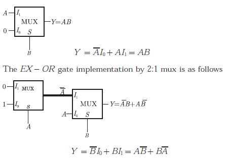
Q5. What are the minimum number of 2- to -1 multiplexers required to generate a 2- input AND gate and a 2- input Ex-OR gate
Answer : Option A
Explaination / Solution:
The AND gate implementation by 2:1 mux is as follows
Q6. A message signal m(t) = cos 200πt + 4cosπt modulates the carrier
c(t) = coe 2πfct where fc = 1MHz to produce an AM signal. For demodulating
the generated AM signal using an envelope detector, the time constant RC of
the detector circuit should satisfy
Answer : Option B
Explaination / Solution:
Highest frequency component in m(t) is 

Carrier frequency fc = 1 MHz
For Envelope detector condition
Q7. 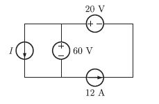
In the interconnection of ideal sources shown in the figure, it is known that the 60 V source is absorbing power.
Which of the following can be the value of the current source I ?
Answer : Option A
Explaination / Solution:
Circuit is as shown below
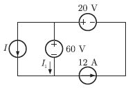
Since 60 V source is absorbing power. So, in 60 V source current flows from + to - ve direction So,
I + I1 = 12
I = 12 - I1
I is always less then 12 A So, only option (A) satisfies this conditions.
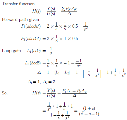
Q8. Assign output of each integrator by a state variable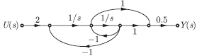
The transfer function of the system is
Answer : Option C
Explaination / Solution:
By masson’s gain formula
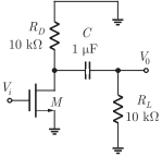
Q9. The ac schematic of an NMOS common-source state is shown in the figure
below, where part of the biasing circuits has been omitted for simplicity. For the
n-channel MOSFET M, the transconductance  and body effect
and channel length modulation effect are to be neglected. The lower cutoff
frequency in HZ of the circuit is approximately at
and body effect
and channel length modulation effect are to be neglected. The lower cutoff
frequency in HZ of the circuit is approximately at
and body effect
and channel length modulation effect are to be neglected. The lower cutoff
frequency in HZ of the circuit is approximately at
Answer : Option A
Explaination / Solution:
No Explaination.
Q10. Let x(t) be a continuous time periodic signal with fundamental period T = 1 seconds. Let {ak} be the complex Fourier series coefficients of x(t), where k is integer valued. Consider the following statements about x(3t):
I. The complex Fourier series coefficients of x(3t) are {ak} where k is integer valued
II. The complex Fourier series coefficients of x(3t) are {3ak} where k is integer valued
III. The fundamental angular frequency of x(3t) is 6𝜋 rad/s
For the three statements above, which one of the following is correct?
Answer : Option B
Explaination / Solution:
Fourier series coefficient ak is unaffected by scaling operating. Thus (I) is true and (II) is false.
T = 1sec for x(t) and if it compressed by '3' then the resultant period T = 1/3
Fundamental frequency = 2𝜋/T1= = 6𝜋 rad/sec
Thus (III) is correct.
