Electronics Engineering - Online Test
Q1. 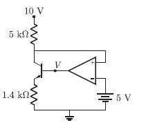
In the circuit shown below, the op-amp is ideal, the transistor has VBE = 0.6 V and β= 150. Decide whether the feedback in the circuit is positive or negative and determine the voltage V at the output of the op-amp.
Answer : Option D
Explaination / Solution:
The circuit is shown in fig below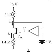
Q2. The Column-I lists the attributes and the Column-II lists the modulation systems. Match the attribute to the modulation system that best meets it
Column-I
P. Power efficient transmission of signals
Q. Most bandwidth efficient transmission of voice signals
R. Simplest receiver structure
S. Bandwidth efficient transmission of signals with Significant dc component
Column-II
1. Conventional AM
2. FM
3. VSB
4. SSB-SC
Answer : Option B
Explaination / Solution:
In FM the amplitude is constant and power is efficient transmitted. No variation in power.
There is most bandwidth efficient transmission in SSB- SC. because we transmit only one side band.
Simple Diode in Non linear region ( Square law ) is used in conventional AM that is simplest receiver structure.
In VSB dc. component exists.
Q3. For parallel RLC circuit, which one of the following statements is NOT correct ?
Answer : Option D
Explaination / Solution:
A parallel RLC circuit is shown below :
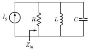
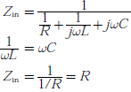
Input impedance
Q4.
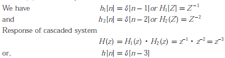
Two discrete time system with impulse response h1[n] = 𝛿[n - 1] and h2[n] = 𝛿[n - 2] are connected in cascade. The overall impulse response of the cascaded system is
Answer : Option C
Explaination / Solution:
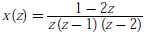
Q5. The residues of a complex function  at its poles are
at its poles are
Answer : Option C
Explaination / Solution:
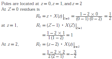
Q6. What is the voltage Vout in the following circuit?
Answer : Option C
Explaination / Solution:
The transfer characteristics of the CMOS inverter is as follows
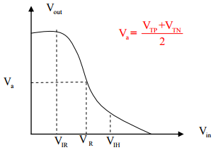

Since the inverter is connected in feedback loop formed by connecting
10XΩ resistor between
the output and input, the output goes and stays at the middle of the characteristics
Va Switching threshold of inverter
Q7. A 3-input majority gate is defined by the logic function M(a,b,c) = ab + bc + ca. Which one of the following gates is represented by the function 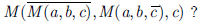
Answer : Option B
Explaination / Solution:
3 input majority gate is given as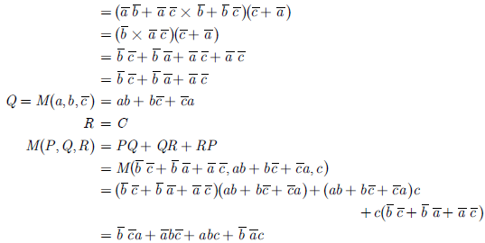
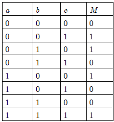
M(a,b,c) = ab + bc + ca
We have to obtain 
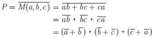
We obtain truth table for the function as
So, the function is odd number of 1’s detector. This function represent the 3-input XOR gate.
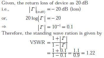
Q8. The return loss of a device is found to be 20 dB. The voltage standing wave ratio (VSWR) and magnitude of reflection coefficient are respectively
Answer : Option A
Explaination / Solution:
Q9. 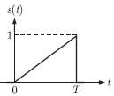
Consider the pulse shape s(t) as shown. The impulse response h(t) of the filter matched to this pulse is
Answer : Option C
Explaination / Solution:
Impulse response of the matched filter is given by


Q10. 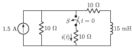
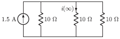
In the circuit shown, the switch S is open for a long time and is closed at t = 0. The current i (t) for t ≥ 0+is
Answer : Option A
Explaination / Solution:
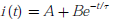
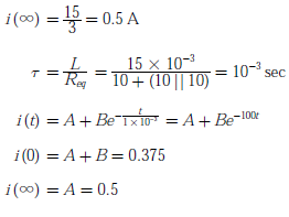
When the switch S is open for a long time before t < 0, the circuit is
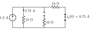
At t = 0, inductor current does not change simultaneously, So the circuit is
Current is resistor (AB)
i(0) = 0.75/2 = 0.375 A
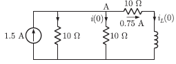
Similarly for steady state the circuit is as shown below
B = 0.375 - 0.5 =- 0.125
