Electronics Engineering - Online Test
Q1. 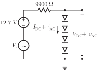
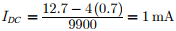
The bias current IDC through the diodes is
Answer : Option A
Explaination / Solution:
The current flows in the circuit if all the diodes are forward biased. In forward biased there will be 0 7. V drop across each diode.
Q2. 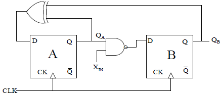
A finite state machine (FSM) is implemented using the D flip-flops A and B, and logic gates, as shown in the figure below. The four possible states of the FSM are QA QB = 00,01,10 and 11.
Assume that XIN is held at a constant logic level throughout the operation of the FSM. When the FSM is initialized to the state QA QB = 00 and clocked, after a few clock cycles, it starts cycling through
Answer : Option D
Explaination / Solution:
In given diagram
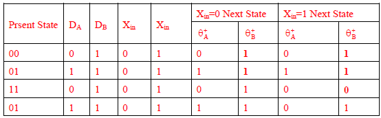
When Xin = 0 2 State
When Xin =1 3 State
Q3. The Fourier series of a real periodic function has only (P) cosine terms if it is even (Q) sine terms if it is even (R) cosine terms if it is odd (S) sine terms if it is odd Which of the above statements are correct ?
Answer : Option A
Explaination / Solution:
The Fourier series of a real periodic function has only cosine terms if it is even and sine terms if it is odd.
Q4.
A band-limited signal with a maximum frequency of 5 kHz is to be sampled. According to the sampling theorem, the sampling frequency which is not valid
Answer : Option A
Explaination / Solution:
Given, the maximum frequency of the band-limited signal
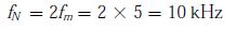
fm = 5 kHz
According to the Nyquist sampling theorem, the sampling frequency must be greater than the Nyquist frequency which is given as
So, the sampling frequency fs must satisfy
only the option (A) does’nt satisfy the condition therefore, 5K HZ is not a valid sampling frequency.
Q5. 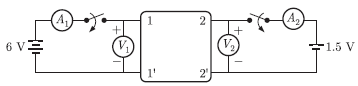
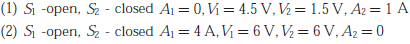
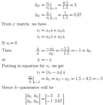
A two-port network shown below is excited by external DC source. The voltage and the current are measured with voltmeters V1,V2 and ammeters. A1,A2 (all assumed to be ideal), as indicated
Under following conditions, the readings obtained are:
The h-parameter matrix for this network is
Answer : Option A
Explaination / Solution:
From the problem statement we have
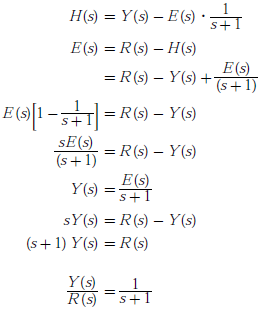
Q6. The transfer function Y(s)/R(s) of the system shown is
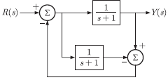
Answer : Option B
Explaination / Solution:
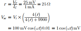
Q7. 
The ac output voltage Vac is
Answer : Option B
Explaination / Solution:
The forward resistance of each diode is
Q8. The following FIVE instructions were executed on an 8085 microprocessor.
MVI A, 33H
MVI B, 78H
ADD B
CMA
ANI 32H
The Accumulator value immediately after the execution of the fifth instruction is
Answer : Option B
Explaination / Solution:
MVI A, 33H A⟵33H
MVI B, 78H B⟵78H
ADD B B⟵ABH
CMA A⟵54H
ANI 32H A⟵10H
A⟶0011 0011 A⟶1010 1011 0101 0100
B⟶0111 1000 B⟶0101 0100 0011 0010
1010 1011 0001 0000
Q9. The ROC of z -transform of the discrete time sequence 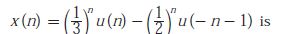
Answer : Option A
Explaination / Solution:
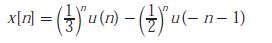
Taking z transform we have

Taking z transform we have
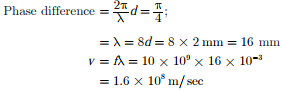
Q10. A transmission line of characteristic impedance 50Ω is terminated by a 50 W load. When excited by a sinusoidal voltage source at 10 GHz, the phase difference between two points spaced 2 mm apart on the line is found to be π/4 radians. The phase velocity of the wave along the line is
Answer : Option C
Explaination / Solution:
We have d = 2 mm and f = 10 GHz