Electronics Engineering - Online Test
Q1. 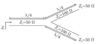
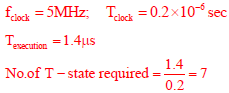
A transmission line terminates in two branches, each of length  as shown. The branches are terminated by 50W loads. The lines are lossless and have the characteristic impedances shown. Determine the impedance Zi as seen by the source.
Answer : Option D
Explaination / Solution:
The transmission line are as shown below. Length of all line is 
Q2. The magnitude plot of a rational transfer function G(s) with real coefficients is shown below. Which of the following compensators has such a magnitude plot ?
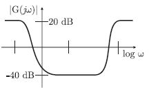
Answer : Option C
Explaination / Solution:
This compensator is roughly equivalent to combining lead and lad compensators in the same design and it is referred also as PID compensator.
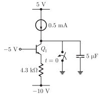
Q3. For the BJT QL in the circuit shown below,  The
switch is initially closed. At time t = 0, the switch is opened. The time t at
which Q1 leaves the active region is
The
switch is initially closed. At time t = 0, the switch is opened. The time t at
which Q1 leaves the active region is
The
switch is initially closed. At time t = 0, the switch is opened. The time t at
which Q1 leaves the active region is
Answer : Option C
Explaination / Solution:
Applying KCL at collector
with time, the capacitor charges and voltage across collector changes from 0
towards negative.
Q4. 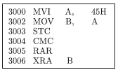
For the 8085 assembly language program given below, the content of the accumulator after the execution of the program is
Answer : Option C
Explaination / Solution:
By executing instruction one by one

Q5.
Let x(t) be the input and y(t) be the output of a continuous time system.
Match the system properties P1, P2 and P3 with system relations R1, R2, R3, R4
Properties Relations
P1 : Linear but NOT time - invariant R1 : y(t) = t2x(t)
P2 : Time - invariant but NOT linear R2 : y(t) = t|x(t)|
P3 : Linear and time - invariant R3 : y(t) = |x(t)|
R4 : y(t) = x(t-5)
Answer : Option B
Explaination / Solution:
Mode function are not linear. Thus y(t) = |x(t)| is not linear but this functions is
time invariant. Option (A) and (B) may be correct.
The y(t) = t|x(t)| is not linear, thus option (B) is wrong and (a) is correct. We
can see that
R1 : y(t) = t2x(t) Linear and time variant.
R2 : y(t) = t|x(t)| Non linear and time variant.
R3 : y(t) = |x(t)| Non linear and time invariant.
R4 : y(t) = x(t-5) Linear and time invariant.
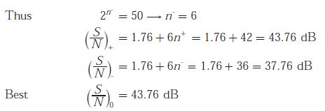
Q6. The amplitude of a random signal is uniformly distributed between -5 V and 5 V.If the signal to quantization noise ratio required in uniformly quantizing the signal is 43.5 dB, the step of the quantization is approximately
Answer : Option C
Explaination / Solution:
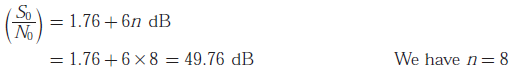
Q7. A speed signal, band limited to 4 kHz and peak voltage varying between +5 V and -5 V, is sampled at the Nyquist rate. Each sample is quantized and represented by 8 bits.
Assuming the signal to be uniformly distributed between its peak to peak value, the signal to noise ratio at the quantizer output is
Answer : Option C
Explaination / Solution:
Q8. 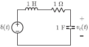
The following series RLC circuit with zero conditions is excited by a unit impulse functions 𝛿(t).
For t > 0, the output voltage vc(t) is
Answer : Option D
Explaination / Solution:
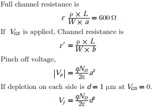
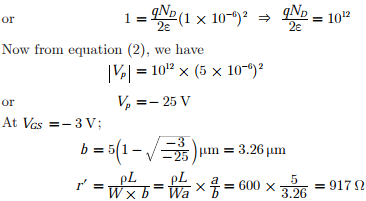
Q9. The channel resistance of an N-channel JFET shown in the figure below is 600Ω when the full channel thickness (tch) of 10μm is available for conduction. The
built-in voltage of the gate P+ N junction (Vbi) is -1 V. When the gate to source
voltage (VGS) is 0 V, the channel is depleted by 1 μm on each side due to the built
in voltage and hence the thickness available for conduction is only 8 μm
The channel resistance when VGS = -3 V is
Answer : Option B
Explaination / Solution:
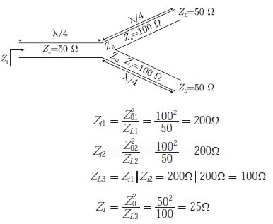
Q10. The clock frequency of an 8085 microprocessor is 5 MHz. If the time required to execute an instruction is 1.4 μs, then the number of T-states needed for executing the instruction is
Answer : Option C
Explaination / Solution: