Electronics Engineering - Online Test
Q1. For linear time invariant systems, that are Bounded Input Bounded stable, which one of the following statement is TRUE?
Answer : Option B
Explaination / Solution:
No Explaination.
Q2. Consider a signal defined by
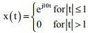
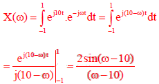
Its Fourier Transform is
Answer : Option A
Explaination / Solution:
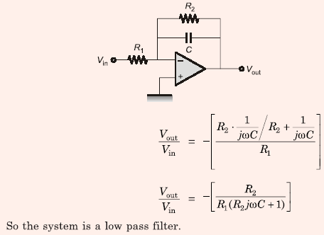
Q3. The circuit shown below is an example of a
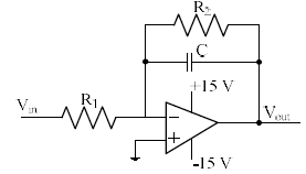
Answer : Option A
Explaination / Solution:
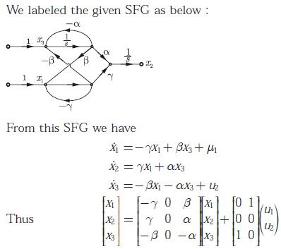
Q4. A signal flow graph of a system is given below
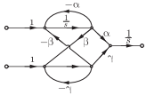
The set of equalities that corresponds to this signal flow graph is
Answer : Option C
Explaination / Solution:
Q5. Consider the Schmidt trigger circuit shown below
A triangular wave which goes from -12 to 12 V is applied to the inverting input
of OPMAP. Assume that the output of the OPAMP swings from +15 V to -15 V.
The voltage at the non-inverting input switches between
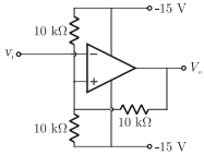
Answer : Option C
Explaination / Solution:
Let the voltage at non inverting terminal be V1, then after applying KCL at non
inverting terminal side we have
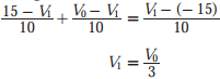
If V0 swings from -15 to +15 V then V1 swings between -5 V to +5 V.
Q6. Consider the following assertions.
S1 : For Zener effect to occur, a very abrupt junction is required.
S2 : For quantum tunneling to occur, a very narrow energy barrier is required.
Which of the following is correct ?
Answer : Option A
Explaination / Solution:
No Explaination.
Q7. 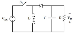
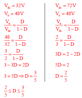
The input voltage VDC of the buck-boost converter
shown below varies from 32 V to 72 V. Assume that
all components are ideal, inductor current is
continuous, and output voltage is ripple free. The
range of duty ratio D of the converter for which the
magnitude of the steady state output voltage remains
constant at 48 V is
Answer : Option A
Explaination / Solution:
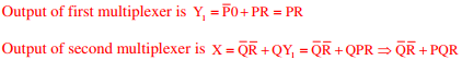
Q8. Consider the two cascaded 2-to-1 multiplexers as shown in the figure.
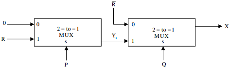
The minimal sum of products form of the output X is
Answer : Option D
Explaination / Solution:
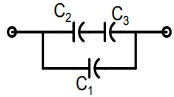
Q9. Three capacitors C1, C2, and C3, whose values are 10µF, 5µF, and 2µF respectively, have
breakdown voltages of 10V, 5V, and 2V respectively. For the interconnection shown, the maximum
safe voltage in Volts that can be applied across the combination and the corresponding total charge
in µC stored in the effective capacitance across the terminals are respectively
Answer : Option C
Explaination / Solution:
No Explaination.
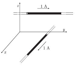
Q10. Two infinitely long wires carrying current are as shown in the figure below. One wire is in the y - z plane and parallel to the y axis. The other wire is in the x - y plane and parallel to the x - axis. Which components of the resultingmagnetic field are non-zero at the origin ?
Answer : Option D
Explaination / Solution:
Due to 1 A current wire in x - y plane, magnetic field be at origin will be in x direction.
Due to 1 A current wire in y - z plane, magnetic field be at origin will be in z direction.
Thus x and z component is non-zero at origin.
Due to 1 A current wire in y - z plane, magnetic field be at origin will be in z direction.
Thus x and z component is non-zero at origin.
