Electrical Engineering - Online Test
Q1. A 3-input majority gate is defined by the logic function M(a,b,c) = ab + bc + ca. Which one of the following gates is represented by the function 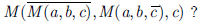
Answer : Option B
Explaination / Solution:
3 input majority gate is given as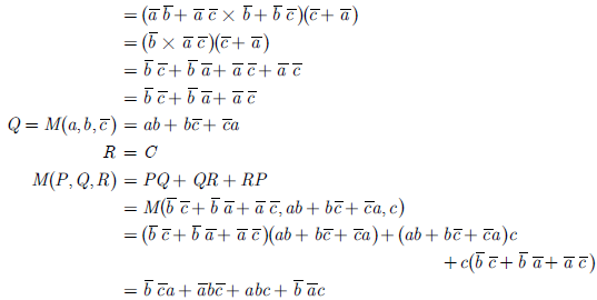
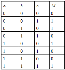
M(a,b,c) = ab + bc + ca
We have to obtain 
We obtain truth table for the function as
So, the function is odd number of 1’s detector. This function represent the 3-input XOR gate.
Q2. An input to a 6-level quantizer has the probability density function f(x) as shown
in the figure. Decision boundaries of the quantizer are chosen so as to maximize the
entropy of the quantizer output. It is given that 3 consecutive decision boundaries
are' −1'. '0 ' and '1'.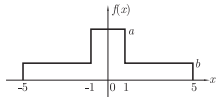
The values of a and b are
Answer : Option A
Explaination / Solution:
Area under the pdf curve must be unity
2a + 4a + 4b = 1
2a + 8b = 1.................................................(1)
For maximum entropy three region must by equivaprobable thus
2a = 4b = 4b...............................................(2)
From (1) and (2) we get
b = 1/12 and a = 1/6
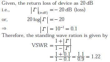
Q3. The return loss of a device is found to be 20 dB. The voltage standing wave ratio (VSWR) and magnitude of reflection coefficient are respectively
Answer : Option A
Explaination / Solution:
Q4. 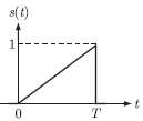
Consider the pulse shape s(t) as shown. The impulse response h(t) of the filter matched to this pulse is
Answer : Option C
Explaination / Solution:
Impulse response of the matched filter is given by


Q5. 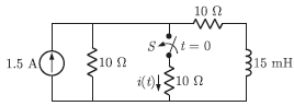
In the circuit shown, the switch S is open for a long time and is closed at t = 0. The current i (t) for t ≥ 0+is
Answer : Option A
Explaination / Solution:
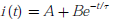
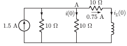
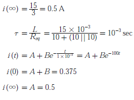
When the switch S is open for a long time before t < 0, the circuit is
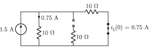
At t = 0, inductor current does not change simultaneously, So the circuit is
Current is resistor (AB)
i(0) = 0.75/2 = 0.375 A
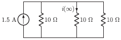
Similarly for steady state the circuit is as shown below
B = 0.375 - 0.5 =- 0.125
Q6. The transfer function of a discrete time LTI system is given by
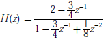
Consider the following statements:
S1: The system is stable and causal for ROC: |z| > 1/2
S2: The system is stable but not causal for ROC: |z| < 1/4
S3: The system is neither stable nor causal for ROC: 1/4 < |z| < 1/2
Which one of the following statements is valid ?
Answer : Option C
Explaination / Solution:
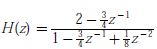
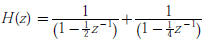

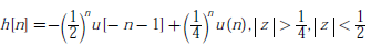
By partial fraction H(z) can be written as
For ROC : |z| > 1/2
Thus system is causal. Since ROC of H(z) includes unit circle, so it is stable also. Hence S1 is True
For ROC : |z| < 1/4
System is not causal. ROC of H(z) does not include unity circle, so it is not stable and S3 is True
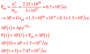
Q7. Consider a silicon sample at T=300K, with a uniform donor density 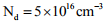 illuminated uniformly such that the optical generation rate
is
illuminated uniformly such that the optical generation rate
is  throughout the sample. The incident radiation is turned off at 𝑡=0.
Assume low-level injection to be valid and ignore surface effects. The carrier lifetimes are
throughout the sample. The incident radiation is turned off at 𝑡=0.
Assume low-level injection to be valid and ignore surface effects. The carrier lifetimes are 
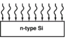
illuminated uniformly such that the optical generation rate
is throughout the sample. The incident radiation is turned off at 𝑡=0.
Assume low-level injection to be valid and ignore surface effects. The carrier lifetimes are The hole concentration at t = 0 and the hole concentration at t = 0.3μs, respectively, are
Answer : Option A
Explaination / Solution:
Q8. The Boolean expression  converted into the canonical product of sum (POS) form is
converted into the canonical product of sum (POS) form is
Answer : Option A
Explaination / Solution:
We have the SOP Boolean form,

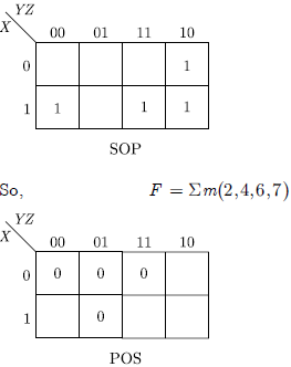
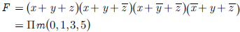
Hence, in POS form, we have
Q9. All the four entries of the 2 × 2 matrix  are nonzero, and one of its
eigenvalue is zero. Which of the following statements is true?
are nonzero, and one of its
eigenvalue is zero. Which of the following statements is true?
are nonzero, and one of its
eigenvalue is zero. Which of the following statements is true?
Answer : Option C
Explaination / Solution:
The product of Eigen value is equal to the determinant of the matrix. Since one
of the Eigen value is zero, the product of Eigen value is zero, thus determinant
of the matrix is zero.
Q10. A transmission line of characteristic impedance 50 W is terminated in a load
impedance ZL. The VSWR of the line is measured as 5 and the first of the
voltage maxima in the line is observed at a distance of λ/4 from the load. The
value of ZL is
Answer : Option A
Explaination / Solution:
Since voltage maxima is observed at a distance of λ/4 from the load and we know
that the separation between one maxima and minima equals to λ/4 so voltage
minima will be observed at the load, Therefore load can not be complex it must
be pure resistive.

also RL = R0/s (since voltage maxima is formed at the load)
RL = (50/5)Ω
