Electrical Engineering - Online Test
Q1. The circuit below implements a filter between the input current ii and the
output voltage v0. Assume that the opamp is ideal. The filter implemented is a
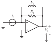
Answer : Option D
Explaination / Solution:
From diagram we can write 
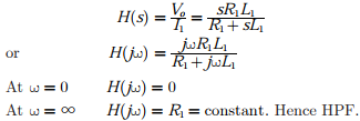
Transfer function
Q2. A current sheet  lies on the dielectric interface x = 0
between two dielectric media with εr1 = 5, μr1 = 1 in Region -1 (x < 0) and εr2 = 5, μr2 = 2 in Region -2(x > 0) . If the magnetic field in Region-1 at
x = 0- is
lies on the dielectric interface x = 0
between two dielectric media with εr1 = 5, μr1 = 1 in Region -1 (x < 0) and εr2 = 5, μr2 = 2 in Region -2(x > 0) . If the magnetic field in Region-1 at
x = 0- is 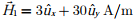 the magnetic field in Region-2 at x = 0+ is
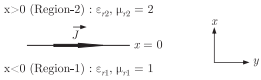
lies on the dielectric interface x = 0
between two dielectric media with εr1 = 5, μr1 = 1 in Region -1 (x < 0) and εr2 = 5, μr2 = 2 in Region -2(x > 0) . If the magnetic field in Region-1 at
x = 0- is the magnetic field in Region-2 at x = 0+ is
Answer : Option A
Explaination / Solution:
From boundary condition
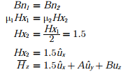
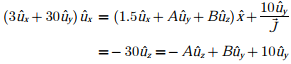
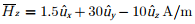
Then from Boundary condition
Comparing we get A = 30 and B =- 10
Q3. 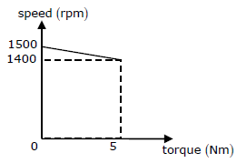
A separately excited DC motor runs at 1500 rpm under no-load with 200V applied to the armature. The field voltage is maintained at its rated value. The speed of the motor, when it delivers at torque of 5 Nm, is 1400 rpm as shown in the figure. The rotational losses and armature reaction are neglected.
For the motor to deliver a torque of 2.5Nm at 1400 rpm, the armature voltage to be applied is
Answer : Option B
Explaination / Solution:
No Explaination.
Q4. For a narrow base PNP BJT, the excess minority carrier concentration (ΔnE for emitter, ΔpB for base. ΔnC for collector) normalized to equilibrium minority carrier concentration (nE0 for emitter, pB0 for base, nC0 for collector) in the quasi-neutral emitter, base and collector regions are shown below. Which one of the following biasing modes is the transistor operating in?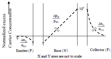
Answer : Option C
Explaination / Solution:
As per the change carrier profile, base – to – emitter junction is reverse bias and base to collector junction is forward bias, so it works in Inverse active.
Q5. X = and Y = are two 5-bit binary numbers represented in two’s complement format. The sum of X and Y represented in two’s complement format using 6 bits is
Answer : Option C
Explaination / Solution:
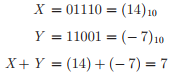

MSB of Y is 1, thus it is negative number and X is positive number
In signed two’s complements from 7 is
Q6. Let A be a 4 × 3 real matrix with rank 2. Which one of the following statement is TRUE?
Answer : Option B
Explaination / Solution:

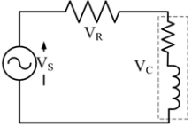
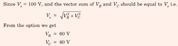
Q7. A resistance and a coil are connected in series and supplied from a single phase, 100 V, 50 Hz ac
source as shown in the figure below. The rms values of plausible voltages across the resistance (VR)
and coil (VC) respectively, in volts, are
Answer : Option D
Explaination / Solution:
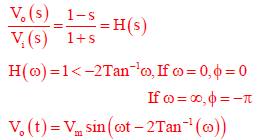
Q8. The transfer function of a system is given by,  Let the output of the system be v0(t) = Vm sin(ωt + φ) for the input vi(t) = Vm sin(ωt). Then the minimum and maximum values of φ (in radians) are respectively
Let the output of the system be v0(t) = Vm sin(ωt + φ) for the input vi(t) = Vm sin(ωt). Then the minimum and maximum values of φ (in radians) are respectively
Answer : Option D
Explaination / Solution:
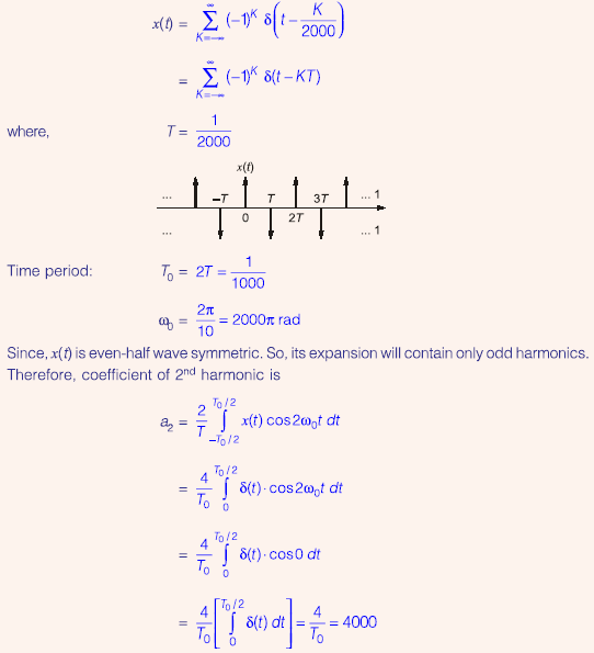
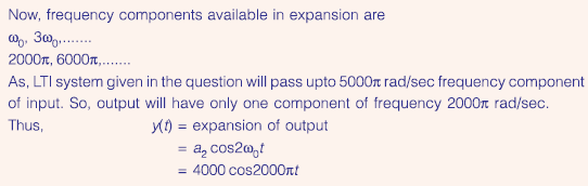
Q9. Let the signal 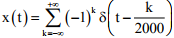 be passed through an LTI system with frequency
response H(𝜔), as given in the figure below
be passed through an LTI system with frequency
response H(𝜔), as given in the figure below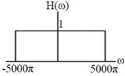
be passed through an LTI system with frequency
response H(𝜔), as given in the figure belowThe Fourier series representation of the output is given as
Answer : Option C
Explaination / Solution:
Q10. 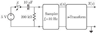
In the following network, the switch is closed at t = 0- and the sampling starts from t = 0. The sampling frequency is 10 Hz.
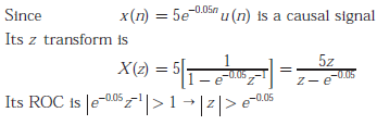
The expression and the region of convergence of the z -transform of the sampled signal are
Answer : Option C
Explaination / Solution: