Electrical Engineering - Online Test
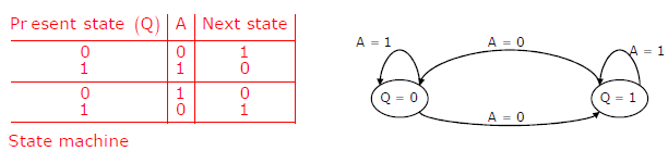
Q1. The state transition diagram for the logic circuit shown is
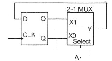
Answer : Option D
Explaination / Solution:
Q2. Consider the following circuit involving three D-type flip-flops used in a certain
type of counter configuration.
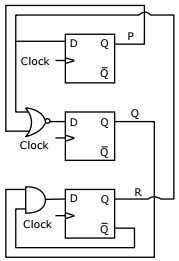
If all the flip-flops were reset to 0 at power on, what is the total number of
distinct outputs (states) represented by PQR generated by the counter?
Answer : Option C
Explaination / Solution:
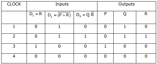
So Total number of distinct outputs is 4
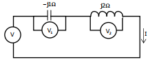
Q3. Three moving iron type voltmeters are connected as shown below. Voltmeter
readings are V, V1 and V2 as indicated. The correct relation among the voltmeter
readings is
Answer : Option B
Explaination / Solution:
No Explaination.
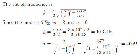
Q4. An air-filled rectangular waveguide has inner dimensions of 3 cm × 2 cm.
The wave impedance of the TE2 mode of propagation in the waveguide at a
frequency of 30 GHz is (free space impedance η0 = 377Ω)
Answer : Option C
Explaination / Solution:
Q5.
The figure shows the high-frequency capacitance - voltage characteristics of Metal/Sio2/silicon (MOS) capacitor having an area of 1 × 10⁻⁴ cm2. Assume that the permittivities (ε0εr) of silicon and Sio are 1 × 10-12 F/cm and 3.5 × 10⁻¹³ F/ cm respectively.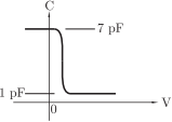
Consider the following statements about the C − V characteristics plot :
S1 : The MOS capacitor has as n-type substrate
S2 : If positive charges are introduced in the oxide, the C − V polt will shift to the left.
Then which of the following is true?
Answer : Option C
Explaination / Solution:
Depletion region will not be formed if the MOS capacitor has n type substrate but from C-V characteristics, C reduces if V is increased. Thus depletion region must be formed. Hence S1 is false
If positive charges is introduced in the oxide layer, then to equalize the effect the applied voltage V must be reduced. Thus the C − V plot moves to the left. Hence S2 is true.
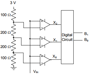
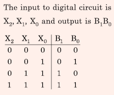
Q6. A 2-bit flash Analog to Digital Converter (ADC) is given below. The input is 0 ≤ VIN ≤ 3 Volts.
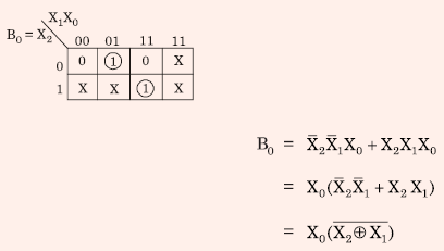
The expression for the LSB of the output B0 as a Boolean function of X2, X1, and X0 is
Answer : Option A
Explaination / Solution:
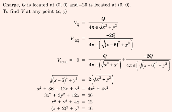
Q7. Two electric charges q and −2q are placed at (0,0) and (6,0) on the x-y plane. The equation of the zero equipotential curve in the x-y plane is
Answer : Option D
Explaination / Solution:
Q8. An RLC circuit with relevant data is given below.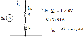
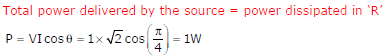
The power dissipated in the resistor R is
Answer : Option B
Explaination / Solution:
Q9. 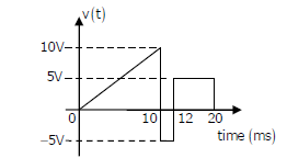
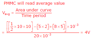
A periodic voltage waveform observed on an oscilloscope across a load is shown. A permanent magnet moving coil (PMMC) meter connected across the same load reads
Answer : Option A
Explaination / Solution:
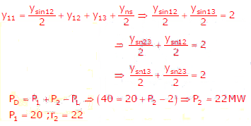
Q10. The bus admittance matrix of a three-bus three-line system is
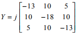
If each transmission line between the two buses is represented by an equivalent π-network, the
magnitude of the shunt susceptance of the line connecting bus 1 and 2 is
Answer : Option B
Explaination / Solution: