Electronics Engineering - Online Test
Q1. A resistance and a coil are connected in series and supplied from a single phase, 100 V, 50 Hz ac
source as shown in the figure below. The rms values of plausible voltages across the resistance (VR)
and coil (VC) respectively, in volts, are
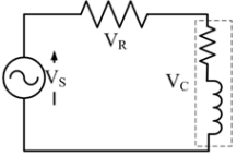
Answer : Option D
Explaination / Solution:
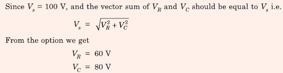
Q2. The transfer function of a system is given by,  Let the output of the system be v0(t) = Vm sin(ωt + φ) for the input vi(t) = Vm sin(ωt). Then the minimum and maximum values of φ (in radians) are respectively
Let the output of the system be v0(t) = Vm sin(ωt + φ) for the input vi(t) = Vm sin(ωt). Then the minimum and maximum values of φ (in radians) are respectively
Answer : Option D
Explaination / Solution:
Q3. Let the signal 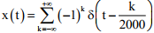 be passed through an LTI system with frequency
response H(𝜔), as given in the figure below
be passed through an LTI system with frequency
response H(𝜔), as given in the figure below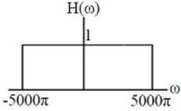
be passed through an LTI system with frequency
response H(𝜔), as given in the figure belowThe Fourier series representation of the output is given as
Answer : Option C
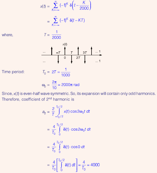
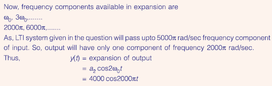
Explaination / Solution:
Q4. 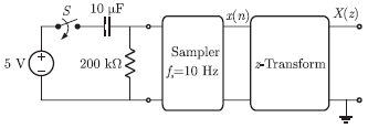
In the following network, the switch is closed at t = 0- and the sampling starts from t = 0. The sampling frequency is 10 Hz.
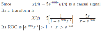
The expression and the region of convergence of the z -transform of the sampled signal are
Answer : Option C
Explaination / Solution:
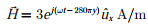
Q5. The electric and magnetic fields for a TEM wave of frequency 14 GHz in a
homogeneous medium of relative permittivity εr and relative permeability
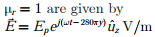
Assuming the speed of light in free space to be 3 × 10⁸ m/s, the intrinsic
impedance of free space to be 120π, the relative permittivity εr of the medium
and the electric field amplitude Ep are
Answer : Option D
Explaination / Solution:
From the expressions of  we can write,
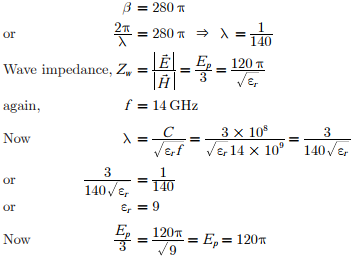
we can write,
Q6. Consider the oscillator circuit shown in the figure. The function of the network (shown in
dotted lines) consisting of the
100kΩ resistor in series with the two diodes connected back-toback
is to:
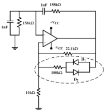
Answer : Option A
Explaination / Solution:
When the output voltage is positive the diode D1 is turned on making 100kΩ resistor to become parallel to 22.1kΩ. So the gain is reduced. When the output voltage becomes negative the diode D2 is turned on thereby again 100kΩ resistor to become parallel to 22.1kΩ. So the gain is reduced. With the use of diodes, the non ideal OP-Amp is made stable to produce steady
Q7. The Miller effect in the context of a Common Emitter amplifier explains
Answer : Option D
Explaination / Solution:
Miller effect increase input capacitance, so that there will be decrease in gain in the high frequency cutoff frequency.
Q8. The Boolean function Y = AB + CD is to be realized using only 2 - input NAND gates. The minimum number of gates required is
Answer : Option B
Explaination / Solution:
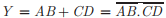
This is SOP form and we require only 3 NAND gate
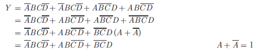
Q9. The Boolean expression  can be
minimized to
can be
minimized to
can be
minimized to
Answer : Option D
Explaination / Solution:
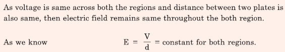
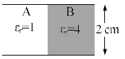
Q10. A parallel plate capacitor filled with two dielectrics is shown in the figure below. If the electric field in the region A is 4 kV/cm, the electric field in the region B, in kV/cm, is
Answer : Option C
Explaination / Solution: