Electronics Engineering - Online Test
Q1.
Consider a straight, infinitely long, current carrying conductor lying on the z-axis. Which one of the following plots (in linear scale) qualitatively represents the dependence of Hϕ on r , where Hϕ is the magnitude of the azimuthal component of magnetic field outside the conductor and r is the radial distance from the conductor ?
Answer : Option C
Explaination / Solution:
No Explaination.
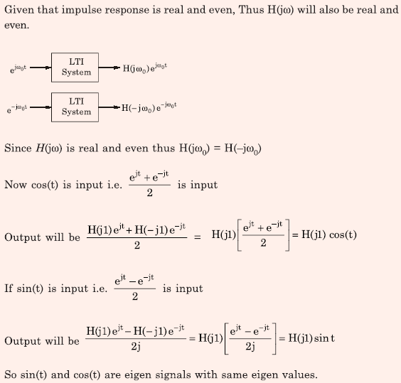
Q2. The output of a continuous-time, linear time-invariant system is denoted by T{x(t)} where x(t) is
the input signal. A signal z(t) is called eigen-signal of the system T , when T{z(t)} = γz(t),
where γ is a complex number, in general, and is called an eigenvalue of T. Suppose the impulse
response of the system T is real and even. Which of the following statements is TRUE?
Answer : Option D
Explaination / Solution:
Q3. Consider a Binary Symmetric Channel (BSC) with probability of error being p. To transmit a bit, say 1, we transmit a sequence of three 1s. The receiver will interpret the received sequence to represent 1 if at least two bits are 1. The probability that the transmitted bit will be received in error is
Answer : Option D
Explaination / Solution:
No Explaination.
Q4. 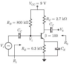
The amplifier circuit shown below uses a silicon transistor. The capacitors Cc and CE can be assumed to be short at signal frequency and effect of output resistance r0 can be ignored. If CE is disconnected from the circuit, which one of the following statements is true
Answer : Option A
Explaination / Solution:
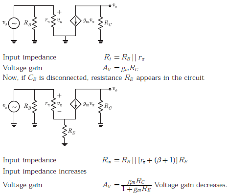
The equivalent circuit of given amplifier circuit (when CE is connected, RE is short-circuited)
Q5. 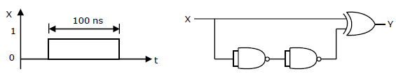
The TTL circuit shown in the figure is fed with the waveform X (also shown). All gates have equal propagation delay of 10ns. The output Y of the circuit is
Answer : Option A
Explaination / Solution:
No Explaination.
Q6. 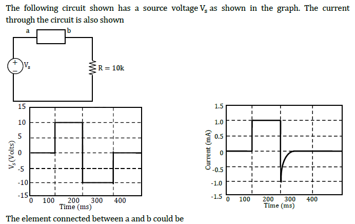
Answer : Option A
Explaination / Solution:
When diode is ON, i=1mA. When diode is OFF, i is zero after small reverse recovery time.
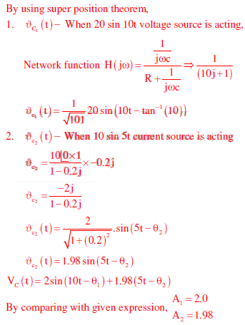
Q7. The voltage across the capacitor, as sown in the figure, is expressed as 
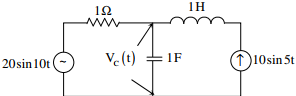
The value of A1 and A2 respectively, are
Answer : Option A
Explaination / Solution:
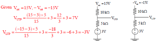
Q8. 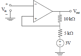
For the operational amplifier circuit shown, the output saturation voltages are ± 15V. The upper and lower threshold voltages for the circuit are, respectively.
Answer : Option B
Explaination / Solution:
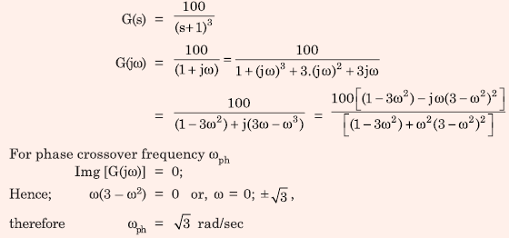
Q9. The phase cross-over frequency of the transfer function 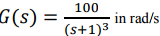 is
is
is
Answer : Option A
Explaination / Solution:
Q10. 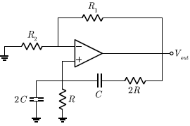
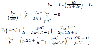
The circuit shown in the figure has an ideal opamp. The oscillation frequency and the condition to sustain the oscillations, respectively, are
Answer : Option D
Explaination / Solution:
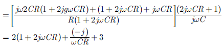
By virtual ground property, we write
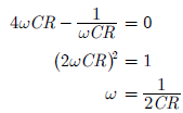
We equate imaginary part to zero, i.e.
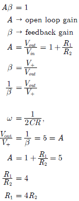
The condition to sustain the oscillation is
