Electronics Engineering - Online Test
Q1. 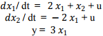
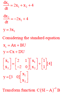
For the system governed by the set of equations:
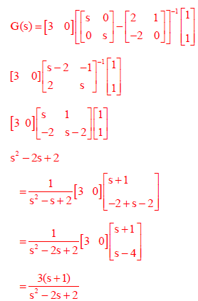
the transfer function Y(s)/U(s) is given by
Answer : Option A
Explaination / Solution:
Q2. An open loop transfer function G(s) of a system is
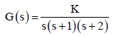
For a unity feedback system, the breakaway point of the root loci on the real axis occurs at,
Answer : Option A
Explaination / Solution:
1+ G= (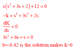
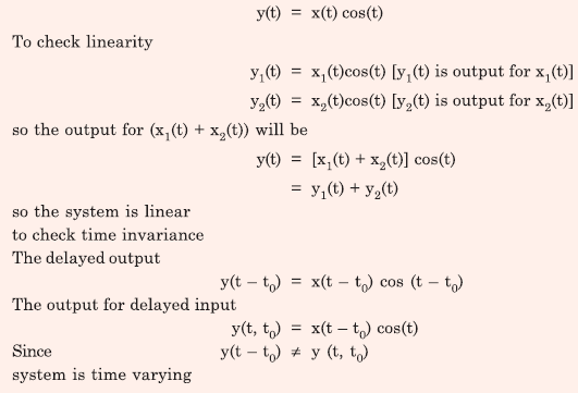
Q3. Consider a continuous-time system with input x(t) and output y(t) given by
y(t) = x(t) cos(t)
This system is
Answer : Option C
Explaination / Solution:
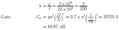
Q4. At 20 GHz, the gain of a parabolic dish antenna of 1 meter and 70% efficiency is
Answer : Option D
Explaination / Solution:
Q5. The logical gate implemented using the circuit shown below where. V1 and V2 are inputs (with
0 V as digital 0 and 5 V as digital 1) and Vout is the output is
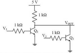
Answer : Option B
Explaination / Solution:
So, this logic level o/p is showing the functionality of NOR-gate.
Q6. Thin gate oxide in a CMOS process in preferably grown using
Answer : Option B
Explaination / Solution:
Dry oxidation is used to achieve high quality oxide growth.
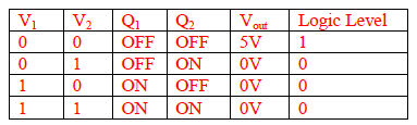
Q7. 
The fully controlled thyristor converter in the figure is fed from a single-phase source. When the firing angle is 0°, the dc output voltage of the converter is 300V. What will be the output voltage for a firing angle of 60°, assuming continuous conduction?
Answer : Option A
Explaination / Solution:
No Explaination.
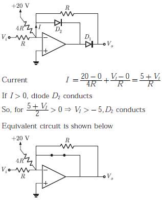
Q8. 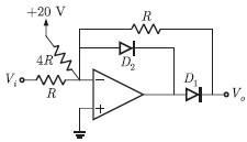
The transfer characteristic for the precision rectifier circuit shown below is (assume ideal OP-AMP and practical diodes)
Answer : Option B
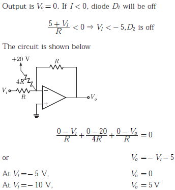
Explaination / Solution:
Q9. 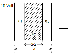
A parallel plate capacitor consisting two dielectric materials is shown in the figure. The middle dielectric slab is place symmetrically with respect to the plates.
If the potential difference between one of the plates and the nearest surface of dielectric
interface is 2Volts, then the ratio ε1:ε2 is
Answer : Option C
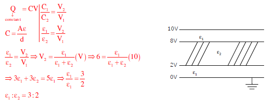
Explaination / Solution:
Q10. 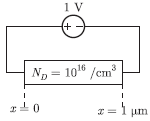
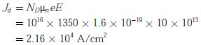
The silicon sample with unit cross-sectional area shown below is in thermal equilibrium. The following information is given: T = 300 K electronic charge = 1.6 × 10⁻¹⁹ C, thermal voltage = 26 mV and electron mobility = 1350 cm2 / V-s
The magnitude of the electron of the electron drift current density at x = 0.5 μm is
Answer : Option A
Explaination / Solution:
Electron drift current density