Electronics Engineering - Online Test
Q1. A discrete system is represented by the difference equation

It has initial condition X1(0) = 1; X2(0) = 0. The pole location of the system for a = 1, are
Answer : Option A
Explaination / Solution:
from the given difference equation,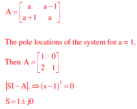
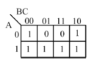
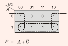
Q2. The output expression for the Karnaugh map shown below is
Answer : Option B
Explaination / Solution:
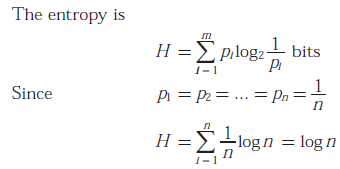
Q3. A memory less source emits n symbols each with a probability p. The entropy of the source as a function of n
Answer : Option A
Explaination / Solution:
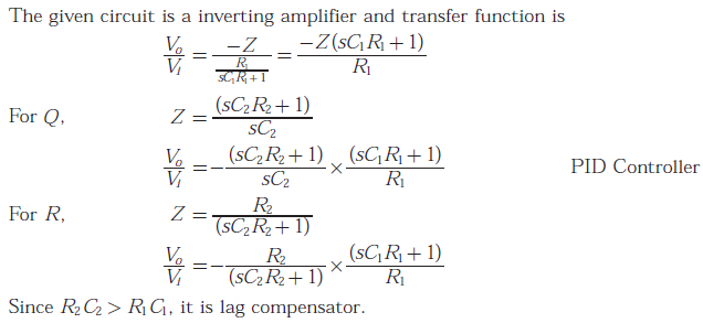
Q4. Group
I gives two possible choices for the impedance Z in the diagram. The circuit
elements in Z satisfy the conditions R2C2 > R1C1. The transfer functions V0/V1 represents a kind of
controller.
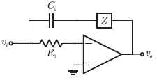
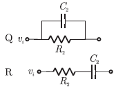
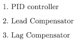
Match the impedances in Group I with the type of controllers in Group II
Group I Group II
Answer : Option B
Explaination / Solution:
Q5. The cross section of a JFET is shown in the following figure. Let Vc be -2
V and let VP be the initial pinch -off voltage. If the width W is doubled (with
other geometrical parameters and doping levels remaining the same), then the
ratio between the mutual trans conductances of the initial and the modified
JFET is
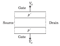
Answer : Option C
Explaination / Solution:
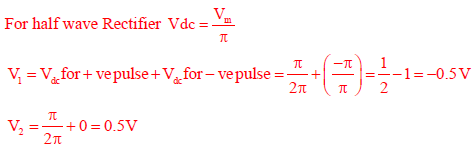
Q6. For the circuit shown in the figure below, assume that diodes D1, D2 and D3 are ideal.
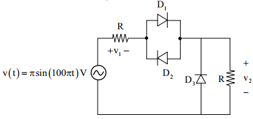
The DC components of voltages v1 and v2, respectively are
Answer : Option B
Explaination / Solution:
Q7. Consider the Boolean operator # with the following properties:
 Then x # y is equivalent to
Then x # y is equivalent to
Answer : Option A
Explaination / Solution:
No Explaination.
Q8. A voltage 1000sinωt Volts is applied across YZ. Assuming ideal diodes, the voltage measured
across WX in Volts is 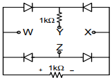
Answer : Option D
Explaination / Solution:
No Explaination.
Q9.
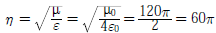
The electric field component of a time harmonic plane EM wave traveling in a nonmagnetic lossless dielectric medium has an amplitude of 1 V/m. If the relative permittivity of the medium is 4, the magnitude of the time-average power density vector (in W/m2) is
Answer : Option C
Explaination / Solution:
Intrinsic impedance of EM wave
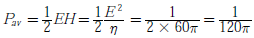
Time average power density
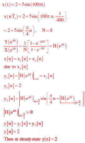
Q10. An input signal x(t) = 2 + 5sin (100πt) is sampled with a sampling frequency of 400 Hz and
applied to the system whose transfer function is represented by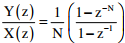
where, N represents the number of samples per cycle. The output y(n) of the system under steady state is
Answer : Option C
Explaination / Solution: