Electrical Engineering - Online Test
Q1. When the output Y in the circuit below is ‘1’, it implies that data has
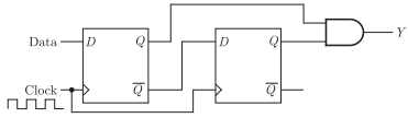
Answer : Option A
Explaination / Solution:
No Explaination.
Q2. Match the inferences X, Y, and Z, about a system, to the corresponding properties of the elements of first column in Routh‟s Table of the system characteristic equation
X: The system is stable … P: … when all elements are positive
Y: The system is unstable … Q: … when any one element is zero
Z: The test breaks down … R: … when there is a change in sign of coefficients
Answer : Option D
Explaination / Solution:
No Explaination.
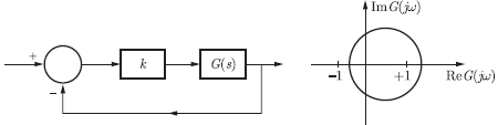
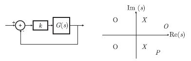
Q3. Consider the feedback system shown in the figure. The Nyquist plot of G (s) is
also shown. Which one of the following conclusions is correct ?
Answer : Option D
Explaination / Solution:
Given the feedback system and the Nyquist plot of G (s)is

For the given system, we have the open loop transfer function as
G (s) = KG (s)
Considering the open loop system G (s) is stable, we have no open loop poles in
right half plane
P = 0
From Nyquist theorem, we know that
N = P - Z
Where N is the number of encirclements of (-1 + j0), P is number of open loop
poles in right half plane, Z is number of closed loop poles in right half plane. For
stability, we must have
Z = 0
N = 0, if closed loop system is stable
N ≠ 0, if closed loop system is unstable
observing the Nyquist plot, we conclude that the plot of KG(s) encircles (-1 + j0)
if K> 1
Hence, N ≠ 0 for sufficient large and positive value of K . Thus, the closedsystem
is unstable for sufficiently large and positive K .
Q4. The trigonometric Fourier series for the waveform f (t) shown below contains
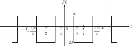
Answer : Option C
Explaination / Solution:
For a function x(t) trigonometric fourier series is
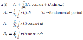

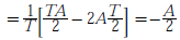
For an even function x(t),Bn = 0
Since given function is even function so coefficient Bn = 0, only cosine and constant
terms are present in its fourier series representation.
Constant term :
Constant term is negative.
Q5. The transfer function 
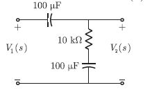
Answer : Option D
Explaination / Solution:
For the given capacitance,  in the circuit, we have the reactance.
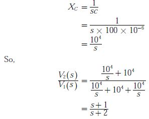
in the circuit, we have the reactance.
Q6. The logic function implemented by the circuit below is (ground implies logic 0)
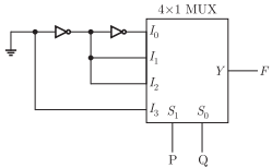
Answer : Option D
Explaination / Solution:

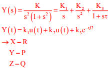
Q7. A first-order low-pass filter of time constant T is excited with different input signals (with zero
initial conditions up to t = 0). Match the excitation signals X, Y, Z with the corresponding time
responses for t ≥ 0:
X: Impulse P: 1 – e-t/T
Y: Unit step Q: t – T(1 – e(-t/T)
Z :Ramp R: e-t/T
Answer : Option C
Explaination / Solution:
In general the first order, L.P.F filter transfer function is  because G(0) = k and G(∞) = ∞ if we take this transfer function as reference and give different input such as
s(t).r(t).u(t)
because G(0) = k and G(∞) = ∞ if we take this transfer function as reference and give different input such as
s(t).r(t).u(t)
because G(0) = k and G(∞) = ∞ if we take this transfer function as reference and give different input such as
s(t).r(t).u(t)
Q8. The feedback configuration and the pole-zero locations of 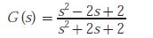 are shown below. The root locus for negative values of k , i.e. for -3 < k < 0, has breakaway/break-in points and angle of departure at pole P (with respect to the
positive real axis) equal to
are shown below. The root locus for negative values of k , i.e. for -3 < k < 0, has breakaway/break-in points and angle of departure at pole P (with respect to thepositive real axis) equal to
Answer : Option B
Explaination / Solution:
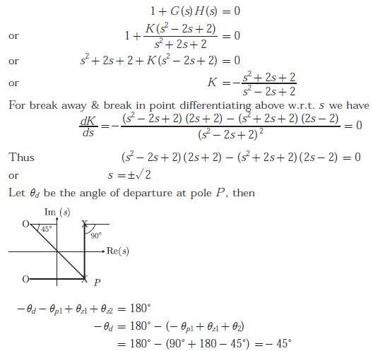
The characteristic equation is
Q9. A function n(x) satisfied the differential equation 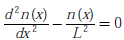 where L is a constant. The boundary conditions are :n(0) = K and n(∞) = 0. The solution to this equation is
where L is a constant. The boundary conditions are :n(0) = K and n(∞) = 0. The solution to this equation is
Answer : Option D
Explaination / Solution:
Given differential equation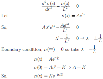
Q10. A source 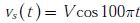 has an internal impedance of
  If a purely resistive load connected to this source has to extract the maximum power out of the source, its value inΩ should be
has an internal impedance of If a purely resistive load connected to this source has to extract the maximum power out of the source, its value inΩ should be
Answer : Option C
Explaination / Solution:
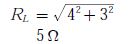
For the purely resistive load, maximum average power is transferred when

where
 is the equivalent thevinin (input) impedance of the circuit. Hence,
we obtain
where
is the equivalent thevinin (input) impedance of the circuit. Hence,we obtain
