Electrical Engineering - Online Test
Q1. Negative feedback in a closed-loop control system DOES NOT
Answer : Option B
Explaination / Solution:
Negative feedback in closed-loop control system does not reduce bandwidth.
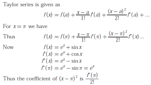
Q2. In the Taylor series expansion of exp(x) + sin(x) about the point x = π, the coefficient of (x-π)2 is
Answer : Option B
Explaination / Solution:
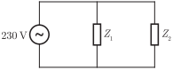
Q3. A 230 V rms source supplies power to two loads connected in parallel. The first load draws 10 kW at 0.8 leading power factor and the second one draws 10 kVA at 0.8 lagging power factor. The complex power delivered by the source is
Answer : Option B
Explaination / Solution:
Consider the circuit diagram for given problem as shown below
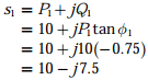
Load delivered to Z1 is
P1 = 10 kW
cos ϕ1
= 0.8, leading
So, we obtain the complex power delivered to Z1 as
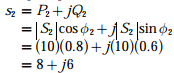
Again, the delivered power to load Z2 as
|s1|= 10 kVA
cos ϕ2 = 0.8, lagging
So, we obtain the complex power delivered to load Z2 as
Hence, the total complex power delivered by the source is
s1 + s2 = (10 – j7.5) + (8
+ j6)
= (18 - j1.5) kVA
Q4. A bulb in a staircase has two switches, one switch being at the ground floor and the other one at the first floor. The bulb can be turned ON and also can be turned OFF by any one of the switches irrespective of the state of the other switch. The logic of switching of the bulb resembles
Answer : Option C
Explaination / Solution:
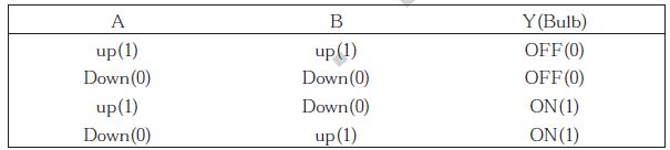

Let A denotes the position of switch at ground floor and B denotes the position of switch at upper floor. The switch can be either in up position or down position.Following are the truth table given for different combinations of A and B
When the switches A and B are both up or both down, output will be zero (i.e.Bulb will be OFF). Any of the switch changes its position leads to the ON state of bulb. Hence, from the truth table, we get
i.e., the XOR gate
Q5. An input  is applied to an LTI system with
impulse response h(t) = u(t). The output is
is applied to an LTI system with
impulse response h(t) = u(t). The output is
is applied to an LTI system with
impulse response h(t) = u(t). The output is
Answer : Option D
Explaination / Solution:
 and h(t) = u(t)
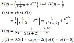
and h(t) = u(t)Taking Laplace Transform we get
Q6. The far-zone power density radiated by a helical antenna is approximated as:

The radiated power density is symmetrical with respect to ϕ and exists only in the upper
hemisphere: C0 is a constant. The power radiated by the antenna (in
watts) and the maximum directivity of the antenna, respectively, are
Answer : Option B
Explaination / Solution:
No Explaination.
Q7. 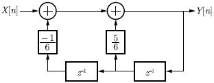
For the discrete-time system shown in the figure, the poles of the system transfer function are located at
Answer : Option C
Explaination / Solution:
We have the discrete time system as shown in figure below.
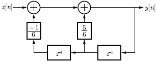
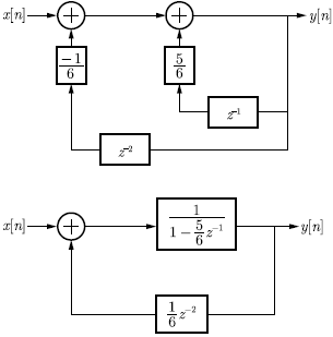
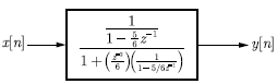
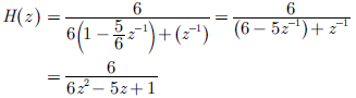
The circuit is minimized as
Hence, poles are at
z = 1/2, 1/3
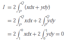
Q8. Consider points P and Q in the x - y plane, with P = (1,0) and Q = (0,1). The line integral 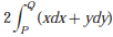 along the semicircle with the line segment PQ as
its diameter
along the semicircle with the line segment PQ as
its diameter
along the semicircle with the line segment PQ as
its diameter
Answer : Option B
Explaination / Solution:
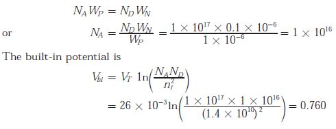
Q9. The built-in potential of the junction
Answer : Option B
Explaination / Solution:
We know that
Q10.
For 8085 microprocessor, the following program is executed.
MVI A, 05H;
MVI B, 05H;
PTR: ADD B;
DCR B;
JNZ PTR;
ADI 03H;
HLT;
At the end of program, accumulator contains
Answer : Option A
Explaination / Solution:
The program is being executed as follows
MVI A, 0.5H; A = 05H
MVI B, 0.5H; B = 05H
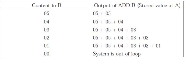
At the next instruction, a loop is being introduced in which for the instruction “DCR B” if the result is zero then it exits from loop so, the loop is executed five times as follows :
i.e., A = 05 + 05 + 04 + 03 + 02 + 01 = 144
At this stage, the 8085 microprocessor exits from the loop and reads the next instruction. i.e., the accumulator is being added to 03 H. Hence, we obtain A = A + 03 H = 14 + 03 = 17 H
