Electrical Engineering - Online Test
Q1. The block diagram of a frequency synthesizer consisting of a Phase Locked Loop (PLL) and a
divide-by-𝑁 counter (comprising ÷2, ÷4, ÷8, ÷16 outputs) is sketched below. The synthesizer is
excited with a 5 kHz signal (Input 1). The free-running frequency of the PLL is set to20 kHz.
Assume that the commutator switch makes contacts repeatedly in the order 1-2-3-4.
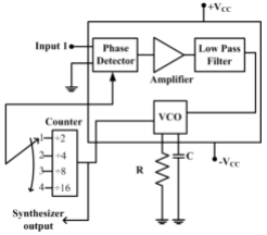
The corresponding frequencies synthesized are:
Answer : Option A
Explaination / Solution:
No Explaination.
Q2. A linear time invariant (LTI) system with the transfer function
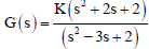
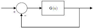
is connected in unity feedback configuration as shown in the figure.
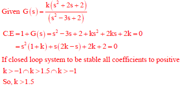
For the closed loop system shown, the root locus for 0 < K < ∞ intersects the imaginary axis for K = 1.5. The closed loop system is stable for
Answer : Option A
Explaination / Solution:
Q3. For maximum power transfer between two cascaded sections of an electrical
network, the relationship between the output impedance Z1 of the first section
to the input impedance Z2 of the second section is
Answer : Option C
Explaination / Solution:
Consider the cascaded network shown below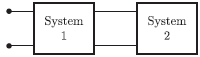
Since, the output impedance of system 1 is Z1 and input impedance of system 2
is Z2. So, we have the equivalent circuit is
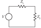
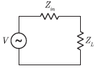
Now, we consider a circuit with internal impedance Zin and load impedance ZL
For maximum power transfer, the condition is
Zin* = Z2
Comparing this condition to cascaded system, we have the required condition for
maximum power transfer as
Z1* = Z2
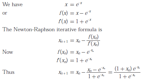
Q4. The recursion relation to solve x = e-x using Newton - Raphson method is
Answer : Option C
Explaination / Solution:
Q5. The digital logic shown in the figure satisfies the given state diagram when Q1 is
connected to input A of the XOR gate.
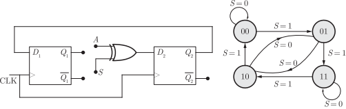
Suppose the XOR gate is replaced by an XNOR gate. Which one of the following
options preserves the state diagram ?
Answer : Option D
Explaination / Solution:
No Explaination.
Q6. A system is defined by its impulse response 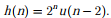 The system is
The system is
Answer : Option B
Explaination / Solution:
No Explaination.
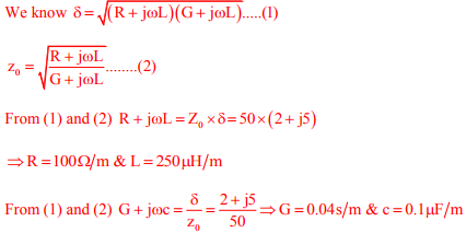
Q7. The propagation constant of a lossy transmission line is (2 + 𝑗5) m-1 and its characteristic impedance is (50 + j0)𝜔 at 𝜔 = 106 rad s-1. The values of the line constants L, C, R, G are, respectively,
Answer : Option B
Explaination / Solution:
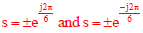
Q8. Which one of the following options correctly describes the locations of the roots of the equation s4 + s2 + 1 = 0 on the complex plane?
Answer : Option C
Explaination / Solution:
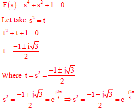
Hence two roots contain RHS and two roots contain LHS plane.
Q9. Consider the configuration shown in the figure which is a portion of a larger
electrical network
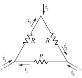
For R = 1Ω and currents i1 = 2 A, i4 =- 1 A, i5 =- 4 A, which one of the
following is TRUE ?
Answer : Option A
Explaination / Solution:
From the circuit, we have
i2 = i4 + i1
= -1 + 2
= 1A
i3 = i5 + i2
= -4 + 1
= -3A
i6 = i1 – i3
= 2 - (-3)
= 5A
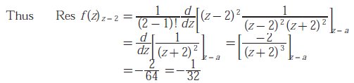
Q10. The residue of the function 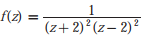 at z = 2 is
at z = 2 is
Answer : Option A
Explaination / Solution: