Electrical Engineering - Online Test
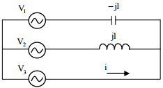
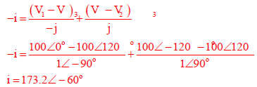
Q1. In the given network V1 = 100∠0°V, V2 = 100∠-120°V, V3 = 100∠+120°V. The phasor
current i (in Ampere) is
Answer : Option A
Explaination / Solution:
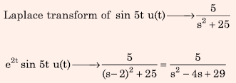
Q2. The Laplace Transform of f(t) = e2t sin(5t) u(t) is
Answer : Option A
Explaination / Solution:
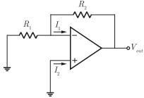
Q3. In the circuit shown, the op-amp has finite input impedance, infinite voltage
gain and zero input offset voltage. The output voltage Vout is
Answer : Option C
Explaination / Solution:
Given that the op-amp has infinite voltage gain, i.e.
AOL =
and zero input offset voltage
VIO = 0
So, we redraw the op-amp circuit as

Hence, the current I1 is drawn through resistance R2. So, the output voltage is
Vout = I1R2
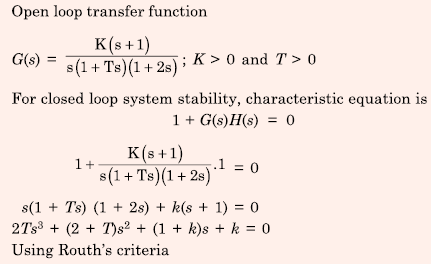
Q4. The open loop transfer function of a unity feedback control system is given by
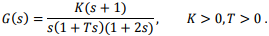
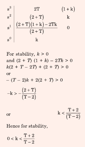
The closed loop system will be stable if,
Answer : Option C
Explaination / Solution:
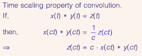
Q5. Let z(t) = x(t) * y(t), where "*" denotes convolution. Let C be a positive real-valued constant. Choose the correct expression for z (ct).
Answer : Option A
Explaination / Solution:
Q6. Consider the following statements regarding the complex Poynting vector  for
the power radiated by a point source in an infinite homogeneous and lossless
medium. Re(
for
the power radiated by a point source in an infinite homogeneous and lossless
medium. Re( ) denotes the real part of
  denotes a spherical surface whose
centre is at the point source, and
denotes a spherical surface whose
centre is at the point source, and  denotes the unit surface normal on S.
Which of the following statements is TRUE?
denotes the unit surface normal on S.
Which of the following statements is TRUE?
Answer : Option C
Explaination / Solution:
Power radiated from any source is constant.
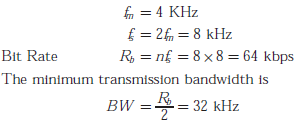
Q7. A speed signal, band limited to 4 kHz and peak voltage varying between +5 V and -5 V, is sampled at the Nyquist rate. Each sample is quantized and represented by 8 bits.
If the bits 0 and 1 are transmitted using bipolar pulses, the minimum bandwidth required for distortion free transmission is
Answer : Option B
Explaination / Solution:
Q8. Power is transferred from system A to system B by an HVDC link as shown in the figure. If the
voltages VAB and VCD are as indicated in the figure, and I > 0, then
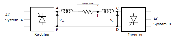
Answer : Option C
Explaination / Solution:
No Explaination.
Q9. 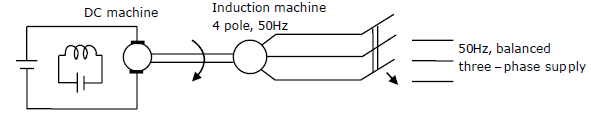
A separately excited dc machine is coupled to a 50Hz, three-phase, 4-pole induction machine as shown in the figure. The dc machine is energized first and the machines rotate at 1600 rpm. Subsequently the induction machine is also connected to a 50Hz, three-phase source, the phase sequence being consistent with the direction of rotation. In steady state,
Answer : Option C
Explaination / Solution:
No Explaination.
Q10. 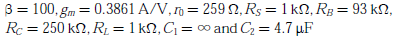
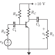
Consider the common emitter amplifier shown below with the following circuit parameters:
The lower cut-off frequency due to C2 is
Answer : Option B
Explaination / Solution:
Cut-off frequency due to C2
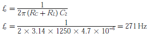
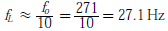
Lower cut-off frequency
