Electrical Engineering - Online Test
Q1. A 3-bus power system is shown in the figure below, where the diagonal elements of Y-bus
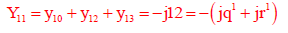
matrix are Y11 = -j12pu, Y22 = -j15pu and Y33 = -j7pu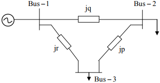
The per unit values of the line reactances p, q and r shown in the figure are
Answer : Option B
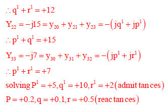
Explaination / Solution:
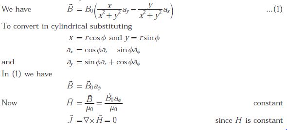
Q2. A magnetic field in air is measured to be 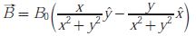 What current distribution leads to this field ?
What current distribution leads to this field ?[Hint : The algebra is trivial in cylindrical coordinates.]
Answer : Option C
Explaination / Solution:
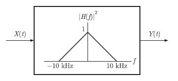
Q3. A white noise process X(t) with two-sided power spectral density 1 X 10⁻¹⁰ W/HZ is input to a filter whose magnitude squared response is shown below.
Answer : Option C
Explaination / Solution:
No Explaination.
Q4. 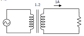
A single-phase transformer has a turns ratio of 1:2, and is connected to a purely resistive load as shown in the figure. The magnetizing current drawn is 1A, and the secondary current is 1A. If core losses and leakage reactance’s are neglected, the primary current is
Answer : Option C
Explaination / Solution:
No Explaination.
Q5.
Compared to a p-n junction with NA = ND = 10-14/cm3, which one of the following statements is TRUE for a p-n junction with NA = ND = 10-20/cm3?
Answer : Option C
Explaination / Solution:
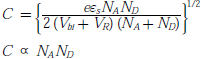
Reverse bias breakdown or Zener effect occurs in highly doped PN junction through tunneling mechanism. In a highly doped PN junction, the conduction and valence bands on opposite sides of the junction are sufficiently close during reverse bias that electron may tunnel directly from the valence band on the p-side into the conduction band on n-side.
Breakdown voltage 
So, breakdown voltage decreases as concentration increases
Depletion capacitance
Depletion capacitance increases as concentration increases
Q6. The following Karnaugh map represent a function F.
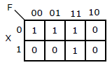
Which of the following circuits is a realization of the above function F?
Answer : Option D
Explaination / Solution:
No Explaination.
Q7. Transformer and emitter follower can both be used for impedance matching at the output of an audio amplifier. The basic relationship between the input power Pin and output power Pout in both the cases is
Answer : Option A
Explaination / Solution:
No Explaination.
Q8. A series RL circuit is excited at t = 0 by closing a switch as shown in the figure.
Assuming zero initial conditions, the value of  is
is
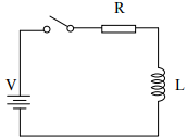
is
Answer : Option D
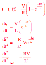
Explaination / Solution:
Q9. 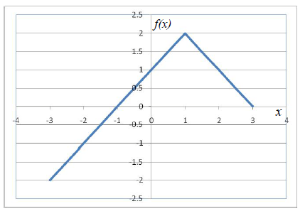
Choose the correct expression for f(x) given in the graph.
Answer : Option C
Explaination / Solution:
No Explaination.
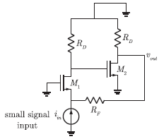
Q10. In the ac equivalent circuit shown in the figure, if iin is the input current and Rf is very larger, the type of feedback is
Answer : Option B
Explaination / Solution:
From the circuit, we observe that output is Vout (Voltage). Feedback is current
through resistance Rf , which is added to input current iin . Thus, the configuration
is voltage-current feedback.
