Electrical Engineering - Online Test
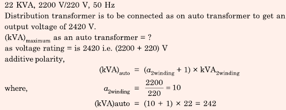
Q1. A single-phase, 22 kVA, 2200 V/ 220 V, 50 Hz, distribution transformer is to be connected as an auto-transformer to get an output voltage of 2420 V. Its maximum kVA rating as an autotransformer is
Answer : Option C
Explaination / Solution:
Q2. A silicon wafer has 100 nm of oxide on it and is furnace at a temperature above
10000 C for further oxidation in dry oxygen. The oxidation rate
Answer : Option D
Explaination / Solution:
No Explaination.
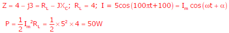
Q3. The average power delivered to an impedance (4 - j3)Ω by a current 5cos(100πt +100) A is
Answer : Option B
Explaination / Solution:
Q4. A solid iron cylinder is placed in a region containing a uniform magnetic field such that the cylinder axis is parallel to the magnetic field direction. The magnetic field lines inside the cylinder will
Answer : Option A
Explaination / Solution:
Flux always chooses less reluctance path. So flux tried to flow inside the conductor and closer to the axis of the cylinder.
Q5. The equation 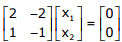 has
has
has
Answer : Option D
Explaination / Solution:
No Explaination.
Q6. The Bode plot of a transfer function G(s) is shown in the figure below.
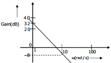
The gain (20 log |G(s)|) is 32 dB and -8 dB at 1 radians/s and 10 radians/s
respectively. The phase is negative for all ω.Then G(s) is
Answer : Option B
Explaination / Solution:
No Explaination.
Q7. A continuous random variable X has a probability density function  is
is
is
Answer : Option A
Explaination / Solution:
No Explaination.
Q8. A single-phase transformer has no-load loss of 64 W, as obtained from an open circuit test. When a short-circuit test is performed on it with 90% of the rated currents flowing in its both LV and HV windings, he measured loss is 81 W. The transformer has maximum efficiency when operated at
Answer : Option C
Explaination / Solution:
No Explaination.
Q9. A single-phase load is supplied by a single-phase voltage source. If the current flowing from the load to the source is 10<− 150°A and if the voltage at the load terminals is 100<60°V , then the
Answer : Option B
Explaination / Solution:
No Explaination.
Q10. The Voltage Source Inverter (VSI) shown in the figure below is switched to provide a 50 Hz, square-wave
ac output voltage (v0) across an R-L load. Reference polarity of v0 and reference direction of the output
current i0 are indicated in the figure. It is given that R = 3 Ω, L = 9.55 mH.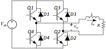
In the interval when v0 < 0 and i0 > 0 the pair of devices which conducts the load current is
Answer : Option D
Explaination / Solution:
No Explaination.
