Analog Circuits - Online Test
Q1. 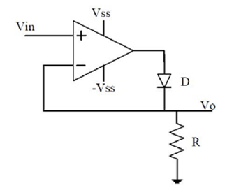
The approximate transfer characteristic for the circuit shown below with an ideal operational amplifier and diode will be
Answer : Option A
Explaination / Solution:
No Explaination.
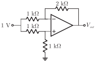
Q2. Given that the op-amp is ideal, the output voltage V0 is
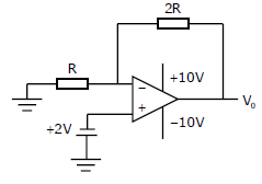
Answer : Option B
Explaination / Solution:
No Explaination.
Q3. The nature of feedback in the op-amp circuit shown is
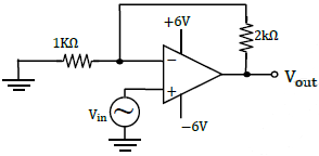
Answer : Option B
Explaination / Solution:
No Explaination.
Q4. The following circuit has R = 10kΩ, C = 10μF . The input voltage is a sinusoid at 50Hz with an
rms value of 10V. Under ideal conditions, the current is from the source is
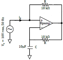
Answer : Option D
Explaination / Solution:
No Explaination.
Q5. In a transconductance amplifier, it is desirable to have
Answer : Option A
Explaination / Solution:
In the transconductance amplifier it is desirable to have large input resistance and large output resistance.
Q6. For the Op-Amp circuit shown in the figure, V is
Answer : Option C
Explaination / Solution:
No Explaination.
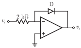
Q7. In the Op-Amp circuit shown, assume that the diode current follows the
equation I = Ise P(V VT). For Vi = V, V = V, and for Vi = V, V = V. The relationship between V and V is
Answer : Option D
Explaination / Solution:
Here the inverting terminal is at virtual ground and the current in resistor and
diode current is equal i.e. 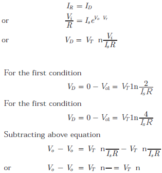
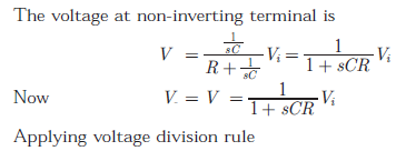
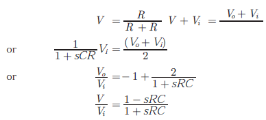
Q8. Consider the Op-Amp circuit shown in the figure. 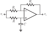
The transfer function V(s) Vi(s)
Answer : Option A
Explaination / Solution:
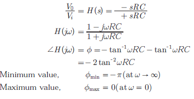
Q9. Consider the Op-Amp circuit shown in the figure.
If  then the minimum and maximum
values of ϕ (in radians) are respectively
then the minimum and maximum
values of ϕ (in radians) are respectively
then the minimum and maximum
values of ϕ (in radians) are respectively
Answer : Option C
Explaination / Solution:
Q10. In the Digital-to-Analog converter circuit shown in the figure below, VR = 1V and R = 1kΩ
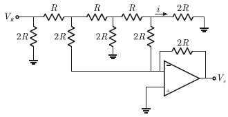
The voltage V is
Answer : Option C
Explaination / Solution:
No Explaination.
