Analog and Digital Electronics - Online Test
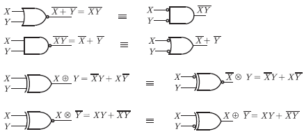
Q1. Match the logic gates in Column A with their equivalents in Column B
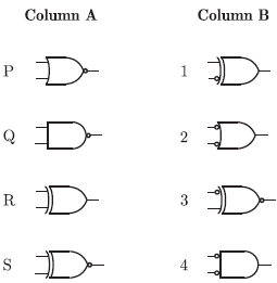
Answer : Option D
Explaination / Solution:
Q2. 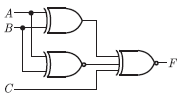
For the output F to be 1 in the logic circuit shown, the input combination should be
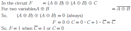
Answer : Option C
Explaination / Solution:
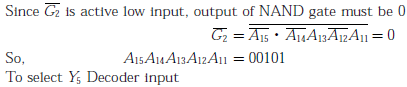
Q3. In the circuit shown, the device connected Y5 can have address in the range

Answer : Option B
Explaination / Solution:
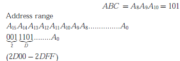
Q4. 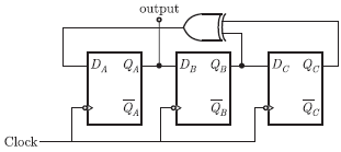
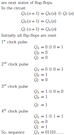
Assuming that the flip-flop are in reset condition initially, the count sequence observed at QA, in the circuit shown is
Answer : Option D
Explaination / Solution:

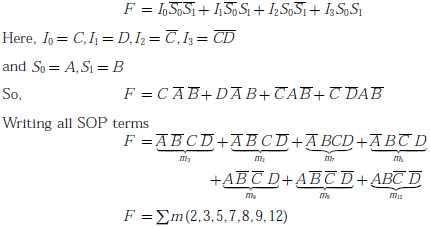
Q5. The Boolean function realized by the logic circuit shown is
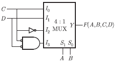
Answer : Option D
Explaination / Solution:
Output of the MUX can be written as
Q6. In a microprocessor, the service routine for a certain interrupt starts from a fixed location of memory which cannot be externally set, but the interrupt can be delayed or rejected Such an interrupt is
Answer : Option D
Explaination / Solution:
Vectored interrupts : Vectored interrupts are those interrupts in which program control transferred to a fixed memory location.
Maskable interrupts : Maskable interrupts are those interrupts which can be rejected or delayed by microprocessor if it is performing some critical task.
Q7. 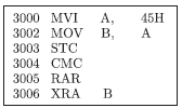
For the 8085 assembly language program given below, the content of the accumulator after the execution of the program is
Answer : Option C
Explaination / Solution:
By executing instruction one by one

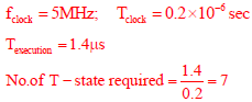
Q8. The clock frequency of an 8085 microprocessor is 5 MHz. If the time required to execute an instruction is 1.4 μs, then the number of T-states needed for executing the instruction is
Answer : Option C
Explaination / Solution:
Q9. 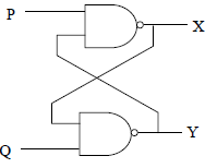
In the latch circuit shown, the NAND gates have non-zero, but unequal propagation delays. The present input condition is: P = Q = '0'. If the input condition is changed simultaneously to P = Q = '1', the outputs X and Y are
Answer : Option B
Explaination / Solution:
Unequal propagation delay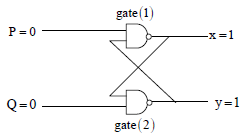
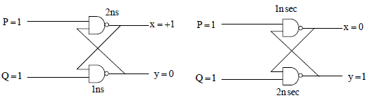
Case I: Case II:
Gate 1⟶2ns Gate 1⟶1nsec
Gate 2⟶1ns Gate 2⟶2nsec
Either x = 1, y = 0 or x = 0, y =1
Q10. 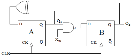
A finite state machine (FSM) is implemented using the D flip-flops A and B, and logic gates, as shown in the figure below. The four possible states of the FSM are QA QB = 00,01,10 and 11.
Assume that XIN is held at a constant logic level throughout the operation of the FSM. When the FSM is initialized to the state QA QB = 00 and clocked, after a few clock cycles, it starts cycling through
Answer : Option D
Explaination / Solution:
In given diagram
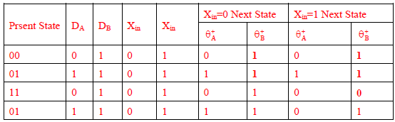
When Xin = 0 2 State
When Xin =1 3 State
