Signals and Systems - Online Test
Q1. The impulse response h(t) of a linear time invariant continuous time system is
described by  where u(-t) denotes the unit
step function, and α and β are real constants. This system is stable if
where u(-t) denotes the unit
step function, and α and β are real constants. This system is stable if
where u(-t) denotes the unit
step function, and α and β are real constants. This system is stable if
Answer : Option D
Explaination / Solution:

This system is stable only when bounded input has bounded output For stability αt < 0 for t > 0 that implies α < 0 and βt > 0 for t > 0 that implies β > 0. Thus, α is negative and β is positive.
Q2. In the ac network shown in the figure, the phasor voltage VA (in Volts) is
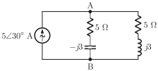
Answer : Option D
Explaination / Solution:
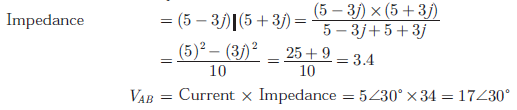
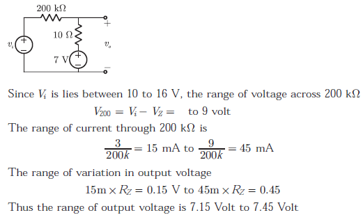
Q3. For the Zener diode shown in the figure, the Zener voltage at knee is 7 V, the
knee current is negligible and the Zener dynamic resistance is 10 Ω. If the input
voltage (Vi) range is from 10 to 16 V, the output voltage (V0) ranges from
Answer : Option C
Explaination / Solution:

Q4. Step responses of a set of three second-order underdamped systems all have the same percentage overshoot. Which of the following diagrams represents the poles of the three systems ?
Answer : Option C
Explaination / Solution:
Transfer function for the given pole zero plot is:

From the plot Re (P1 and P2)>(Z1 and Z2)
So, these are two lead compensator.
Hence both high pass filters and the system is high pass filter
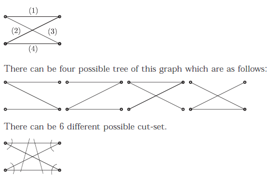
Q5. In the following graph, the number of trees (P) and the number of cut-set (Q) are
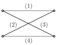
Answer : Option C
Explaination / Solution:
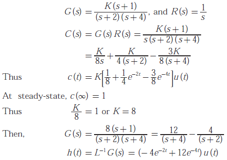
Q6. A linear, time - invariant, causal continuous time system has a rational transfer function with simple poles at s =- 2 and s =- 4 and one simple zero at s =- 1 . A unit step u(t) is applied at the input of the system. At steady state, the output has constant value of 1. The impulse response of this system is
Answer : Option C
Explaination / Solution:
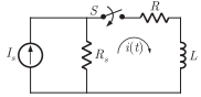
Q7. In the following circuit, the switch S is closed at t = 0. The rate of change of
current  is given by
Answer : Option B
Explaination / Solution:
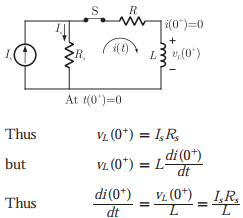
Initially i(0-) = 0 therefore due to inductor i(0+) = 0. Thus all current Is will
flow Is in resistor R and voltage across resistor will be IsRs. The voltage across
inductor will be equal to voltage across Rs as no current flow through R.
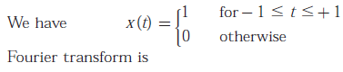
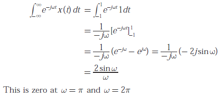
Q8. The signal x(t) is described by
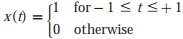
Two of the angular frequencies at which its Fourier transform becomes zero are
Answer : Option A
Explaination / Solution:
Q9. The Thevenin equivalent impedance Zth between the nodes P and Q in the
following circuit is
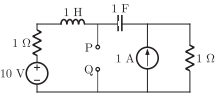
Answer : Option A
Explaination / Solution:
Killing all current source and voltage sources we have,
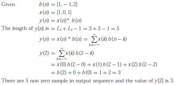
Q10. A discrete time linear shift - invariant system has an impulse response h[n] with h[0] = 1,h[1] =- 1,h[2] = 2, and zero otherwise The system is given an input sequence x[n] with x[0] = x[2] = 1, and zero otherwise. The number of nonzero samples in the output sequence y[n], and the value of y[2] are respectively
Answer : Option D
Explaination / Solution: