Control Systems - Online Test
Q1. Assign output of each integrator by a state variable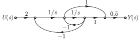
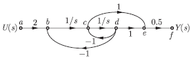
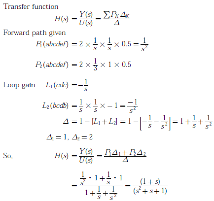
The transfer function of the system is
Answer : Option C
Explaination / Solution:
By masson’s gain formula
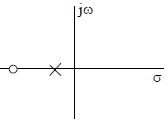
Q2. Which of the following can be pole-zero configuration of a phase-lag controller (lag compensator)?
Answer : Option A
Explaination / Solution:
In phase lag compensator pole is near to j𝜔-axis,
Q3. Consider a stable system with transfer function
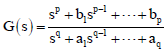
Where b1,
---, bp and a1,
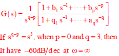
---, aq are real valued constants. The slope of the Bode log magnitude curve of G(s) converges to -60 dB/decade as 𝜔 ⟶ ∞. A possible pair of values for p and q is
Answer : Option A
Explaination / Solution:
Q4. Consider the following statements for continuous-time linear time invariant (LTI) systems.
I. There is no bounded input bounded output (BIBO) stable system with a pole in the right half of the complex plane.
II. There is non causal and BIBO stable system with a pole in the right half of the complex plane.
Which one among the following is correct?
Answer : Option D
Explaination / Solution:
If a system is non-causal then a pole on right half of the s-plane can give BIBO stable system. But for a causal system to be BIBO all poles must lie on left half of the complex plane.
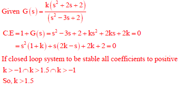
Q5. A linear time invariant (LTI) system with the transfer function
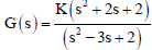
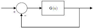
is connected in unity feedback configuration as shown in the figure.
For the closed loop system shown, the root locus for 0 < K < ∞ intersects the imaginary axis for K = 1.5. The closed loop system is stable for
Answer : Option A
Explaination / Solution:
Q6. Which one of the following options correctly describes the locations of the roots of the equation s4 + s2 + 1 = 0 on the complex plane?
Answer : Option C
Explaination / Solution:
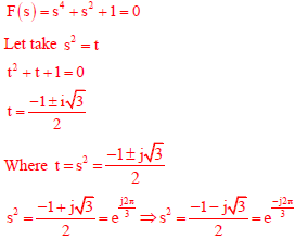
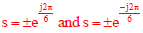
Hence two roots contain RHS and two roots contain LHS plane.
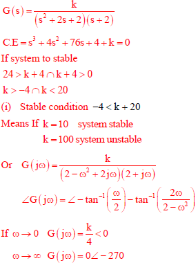
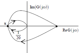
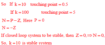
Q7. The Nyquist plot of the transfer function
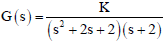
does not encircle the point (1+ j0) for K = 10 but does encircle the point (-1+ j0) for K = 100. Then the closed loop system (having unity gain feedback) is
Answer : Option B
Explaination / Solution:
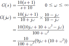
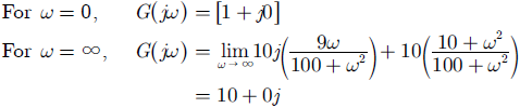
Q8. The polar plot of the transfer function 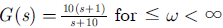 will be in the
will be in the
Answer : Option A
Explaination / Solution:
Q9. Negative feedback in a closed-loop control system DOES NOT
Answer : Option B
Explaination / Solution:
Negative feedback in closed-loop control system does not reduce bandwidth.
Q10. 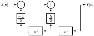
For the discrete-time system shown in the figure, the poles of the system transfer function are located at
Answer : Option C
Explaination / Solution:
We have the discrete time system as shown in figure below.
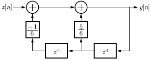
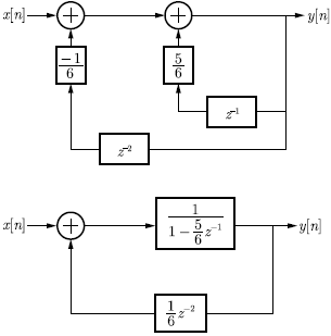
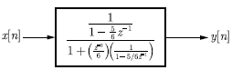
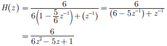
The circuit is minimized as
Hence, poles are at
z = 1/2, 1/3
