Analog and Digital Electronics - Online Test
Q1. The output Y of the logic circuit given below is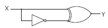
Answer : Option A
Explaination / Solution:
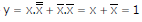
Q2. 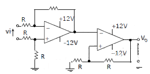
The CORRECT transfer characteristic is
Answer : Option D
Explaination / Solution:
It is a Schmitt trigger and phase shift is zero.
Q3. A low – pass filter with a cut-off frequency of 30Hz is cascaded with a high-pass filter with a cut-off frequency of 20Hz. The resultant system of filters will function as
Answer : Option D
Explaination / Solution:
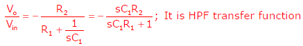
Q4. The circuit shown is a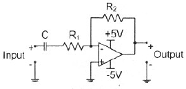
Answer : Option B
Explaination / Solution:
Q5. A portion of the main program to call a subroutine SUB in an 8085 environment is given below.
:
:
LXI D,DISP
LP : CALL SUB
:
It is desired that control be returned to LP+DISP+3 when the RET instruction is executed in the subroutine. The set of instructions that precede the RET instruction in the subroutine are
Answer : Option C
Explaination / Solution:
No Explaination.
Q6. The voltage gain Av of the circuit shown below is
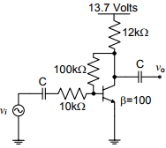
Answer : Option D
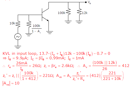
Explaination / Solution:
Q7. A two – bit counter circuit is shown below
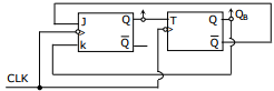
It the state QAQB of the counter at the clock time tn is ‘10’ then the state QAQB of the counter at tn + 3 (after three clock cycles ) will be
Answer : Option C
Explaination / Solution:
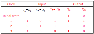
Q8. In the circuit shown below what is the output voltage out (Vout) in Volts if a silicon
transistor Q and an ideal op-amp are used?
Answer : Option B
Explaination / Solution:
No Explaination.
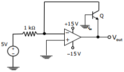
Q9. In the sum of products function f (X, Y, Z) = ∑(2, 3, 4, 5), the prime implicants are
Answer : Option A
Explaination / Solution:
Q10. In the circuit shown below the op-amps are ideal. Then Vout in Volts is
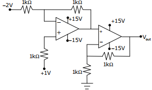
Answer : Option C
Explaination / Solution:
No Explaination.
