Digital Circuits - Online Test
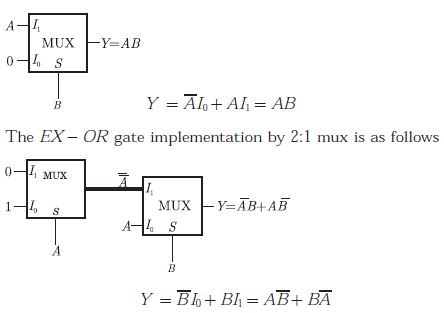
Q1. What are the minimum number of 2- to -1 multiplexers required to generate a 2- input AND gate and a 2- input Ex-OR gate
Answer : Option A
Explaination / Solution:
The AND gate implementation by 2:1 mux is as follows
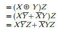
Q2. The Boolean expression 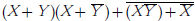 simplifies to
simplifies to
Answer : Option C
Explaination / Solution:
Given the Boolean expression

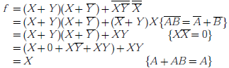
We simplify the expression as
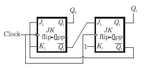
Q3. What are the counting states (Q1,Q2) for the counter shown in the figure below
Answer : Option A
Explaination / Solution:
The given circuit is as follows.
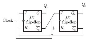
The truth table is as shown below. Sequence is 00, 11, 10, 00 ...
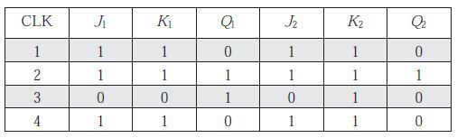
The truth table is as shown below. Sequence is 00, 11, 10, 00 ...
Q4. The output F in the digital logic circuit shown in the figure is

Answer : Option A
Explaination / Solution:
In the logic circuit, the two inputs to the output AND gate are


So, we have the output
Q5. Consider the Boolean function,  . Which one of the following is the complete set of essential prime implicants ?
. Which one of the following is the complete set of essential prime implicants ?
Answer : Option D
Explaination / Solution:
k -map for the Boolean function can be given as

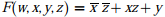
Therefore, the simplified So P from for the Boolean function is
Q6. The digital logic shown in the figure satisfies the given state diagram when Q1 is
connected to input A of the XOR gate.
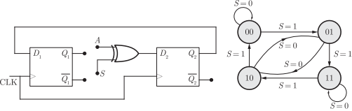
Suppose the XOR gate is replaced by an XNOR gate. Which one of the following
options preserves the state diagram ?
Answer : Option D
Explaination / Solution:
No Explaination.
Q7.
If segments a to g are considered as functions of P1 and P2, then which of the following is correct
Answer : Option B
Explaination / Solution:
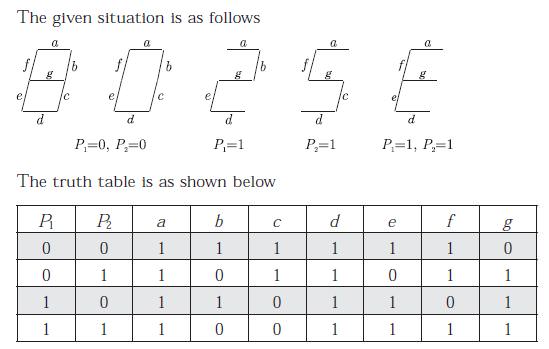
LED d is 1 all condition and also it depends on
d = c + e
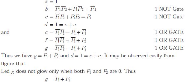
Q8.
What are the minimum numbers of NOT gates and 2 - input OR gates required to design the logic of the driver for this 7 - Segment display
Answer : Option D
Explaination / Solution:
As shown in previous solution 2 NOT gates and 3-OR gates are required.
Q9. A bulb in a staircase has two switches, one switch being at the ground floor and the other one at the first floor. The bulb can be turned ON and also can be turned OFF by any one of the switches irrespective of the state of the other switch. The logic of switching of the bulb resembles
Answer : Option C
Explaination / Solution:
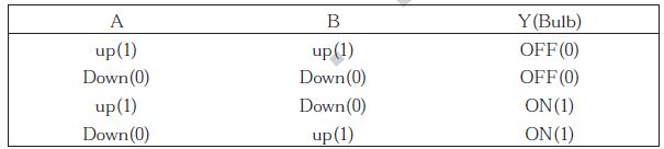

Let A denotes the position of switch at ground floor and B denotes the position of switch at upper floor. The switch can be either in up position or down position.Following are the truth table given for different combinations of A and B
When the switches A and B are both up or both down, output will be zero (i.e.Bulb will be OFF). Any of the switch changes its position leads to the ON state of bulb. Hence, from the truth table, we get
i.e., the XOR gate
Q10.
For 8085 microprocessor, the following program is executed.
MVI A, 05H;
MVI B, 05H;
PTR: ADD B;
DCR B;
JNZ PTR;
ADI 03H;
HLT;
At the end of program, accumulator contains
Answer : Option A
Explaination / Solution:
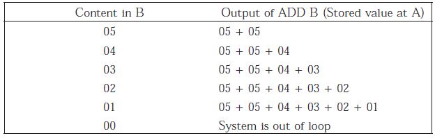
The program is being executed as follows
MVI A, 0.5H; A = 05H
MVI B, 0.5H; B = 05H
At the next instruction, a loop is being introduced in which for the instruction “DCR B” if the result is zero then it exits from loop so, the loop is executed five times as follows :
i.e., A = 05 + 05 + 04 + 03 + 02 + 01 = 144
At this stage, the 8085 microprocessor exits from the loop and reads the next instruction. i.e., the accumulator is being added to 03 H. Hence, we obtain A = A + 03 H = 14 + 03 = 17 H
