Signals and Systems - Online Test
Q1. For maximum power transfer between two cascaded sections of an electrical
network, the relationship between the output impedance Z1 of the first section
to the input impedance Z2 of the second section is
Answer : Option C
Explaination / Solution:
Consider the cascaded network shown below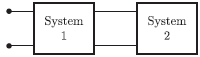
Since, the output impedance of system 1 is Z1 and input impedance of system 2
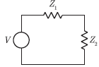
is Z2. So, we have the equivalent circuit is
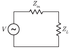
Now, we consider a circuit with internal impedance Zin and load impedance ZL
For maximum power transfer, the condition is
Zin* = Z2
Comparing this condition to cascaded system, we have the required condition for
maximum power transfer as
Z1* = Z2
Q2. A system is defined by its impulse response 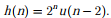 The system is
The system is
Answer : Option B
Explaination / Solution:
No Explaination.
Q3. Consider the configuration shown in the figure which is a portion of a larger
electrical network
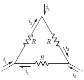
For R = 1Ω and currents i1 = 2 A, i4 =- 1 A, i5 =- 4 A, which one of the
following is TRUE ?
Answer : Option A
Explaination / Solution:
From the circuit, we have
i2 = i4 + i1
= -1 + 2
= 1A
i3 = i5 + i2
= -4 + 1
= -3A
i6 = i1 – i3
= 2 - (-3)
= 5A
Q4.
Assuming zero initial condition, the response y(t) of the system given below to a unit step input u(t) h is
Answer : Option B
Explaination / Solution:
The Laplace transform of unit step fun n is 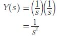
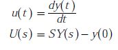

U(s)=1/s
So, the O/P of the system is given as
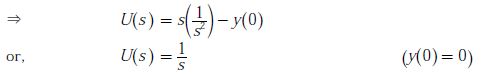
For zero initial condition, we check
Hence, the O/P is correct which is
its inverse Laplace transform is given by
Y(t)=tu(t)
Q5. A two-port network has scattering parameters given by  If the
port-2 of the two port is short circuited, the S11 parameter for the resultant one
If the
port-2 of the two port is short circuited, the S11 parameter for the resultant one
If the
port-2 of the two port is short circuited, the S11 parameter for the resultant one
Answer : Option B
Explaination / Solution:
No Explaination.
Q6. If the unit step response of a network is (1 – e-αt), then its unit impulse response is
Answer : Option A
Explaination / Solution:

Q7. A 230 V rms source supplies power to two loads connected in parallel. The first load draws 10 kW at 0.8 leading power factor and the second one draws 10 kVA at 0.8 lagging power factor. The complex power delivered by the source is
Answer : Option B
Explaination / Solution:
Consider the circuit diagram for given problem as shown below
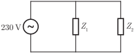
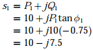
Load delivered to Z1 is
P1 = 10 kW
cos ϕ1
= 0.8, leading
So, we obtain the complex power delivered to Z1 as
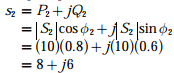
Again, the delivered power to load Z2 as
|s1|= 10 kVA
cos ϕ2 = 0.8, lagging
So, we obtain the complex power delivered to load Z2 as
Hence, the total complex power delivered by the source is
s1 + s2 = (10 – j7.5) + (8
+ j6)
= (18 - j1.5) kVA
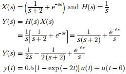
Q8. An input  is applied to an LTI system with
impulse response h(t) = u(t). The output is
is applied to an LTI system with
impulse response h(t) = u(t). The output is
is applied to an LTI system with
impulse response h(t) = u(t). The output is
Answer : Option D
Explaination / Solution:
 and h(t) = u(t)
and h(t) = u(t)Taking Laplace Transform we get
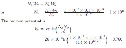
Q9. The built-in potential of the junction
Answer : Option B
Explaination / Solution:
We know that
Q10. Which one of the following is an eigen function of the class of all continuous-time, linear, time-invariant systems u(t) denotes the unit-step function)?
Answer : Option C
Explaination / Solution:
No Explaination.
