Signals and Systems - Online Test
Q1. If the 12 Ω resistor draws a current of 1A as shown in the figure, the value of resistance R is
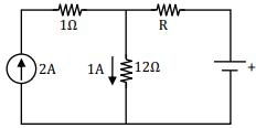
Answer : Option B
Explaination / Solution:
No Explaination.
Q2. A Linear Time Invariant system with an impulse response h(t) produces output y(t)
when input x(t) is applied. When the input x (t−τ) is applied to a system with impulse
response h(t − τ), the output will be
Answer : Option D
Explaination / Solution:
No Explaination.
Q3. The two-port network P shown in the figure has ports 1 and 2, denoted by terminals (a, b) and
(c, d), respectively. It has an impedance matrix Z with parameters denoted by zij. A 1Ω resistor
is connected in series with the network at port 1 as shown in the figure. The impedance matrix
of the modified two-port network (shown as a dashed box) is
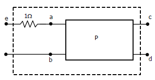
Answer : Option C
Explaination / Solution:
No Explaination.
Q4. If the Laplace transform of a signal 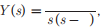 then its final value is
then its final value is
Answer : Option D
Explaination / Solution:
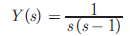
Final value theorem is applicable only when all poles of system lies in left half of S -plane. Here s = 1 is right s −plane pole. Thus it is unbounded.
Q5. The L-C circuit shown in the figure has an inductance L = 1mH and a capacitance
C = 10µF. 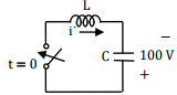
The initial current through the inductor is zero, while the initial capacitor voltage is 100 V. The switch is closed at t = 0. The current i through the circuit is:
Answer : Option D
Explaination / Solution:
No Explaination.
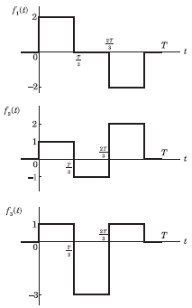
Q6. Three functions f(t), f2(t) and f3(t) which are zero outside the interval [0, T] are
shown in the figure. Which of the following statements is correct?
Answer : Option C
Explaination / Solution:
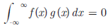
For two orthogonal signal f (x) and g(x)
i.e. common area between f x and g x is zero.
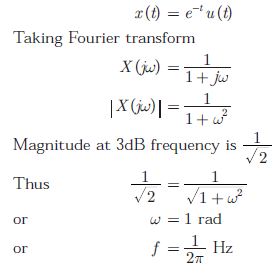
Q7. The 3-dB bandwidth of the low-pass signal e-t u(t), where u(t) is the unit step
function, is given by
Answer : Option A
Explaination / Solution:
Q8. The L-C circuit shown in the figure has an inductance L = 1mH and a capacitance C = 10µF. 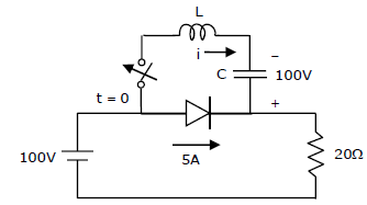
The L – C circuit of Q.9 is used to commutate a thyristor. Which is initially carrying a current of 5 A as shown in the figure below. The values and initial conditions of L and C are the same as in Q.9. The switch is closed at t=0. If the forward drop is negligible, the time taken for the device to turn off is
Answer : Option A
Explaination / Solution:
No Explaination.
Q9. A Hilbert transformer is a
Answer : Option A
Explaination / Solution:
No Explaination.
Q10. The current through the 2 kΩ resistance in the circuit shown is

Answer : Option A
Explaination / Solution:
It is a balanced Wheatstone bridge.
