Signals and Systems - Online Test
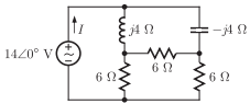
Q1. In the circuit shown below, the current I is equal to
Answer : Option B
Explaination / Solution:
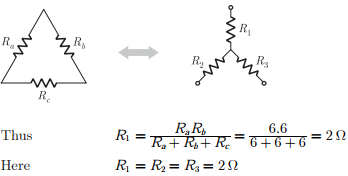
From star delta conversion we have
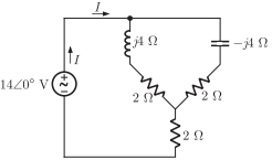
Replacing in circuit we have the circuit shown below :
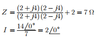
Now the total impedance of circuit is
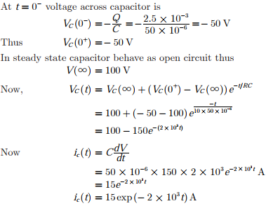
Q2. In the circuit shown below, the initial charge on the capacitor is 2.5 mC, with
the voltage polarity as indicated. The switch is closed at time t = 0. The current i(t) at a time t after the switch is closed is
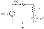
Answer : Option A
Explaination / Solution:
Here we take the current flow direction as positive.
Q3. A network consisting of a finite number of linear resistor (R), inductor (L), and capacitor (C)
elements, connected all in series or all in parallel, is excited with a source of the form
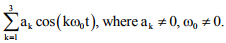
The source has nonzero impedance. Which one of the following is a possible form of the
output measured across a resistor in the network?
Answer : Option A
Explaination / Solution:
The property of any LTI system or network is if the excitation contains „n‟ number of different
frequency then the response also contains exactly n number of different frequency term and the
output frequency and input frequency must be same however depending on components there
is a possible change in amplitude and phase but never the frequency.
⟶ If the source has 3 frequency terms as given  then any voltage or any current of any element should have also 3 terms based on this option (B) and (D) are eliminated.
then any voltage or any current of any element should have also 3 terms based on this option (B) and (D) are eliminated.⟶ If we take option (C). It has 3 frequency term but it also suggest there is a phase change so ϕk but amplitude must be same as input as ak is present which may not be true always.
⟶ So option (A) is correct, as it suggest frequency term of output and inputs are same with
possible change in amplitude and phase, because we have (bk and ϕk ).
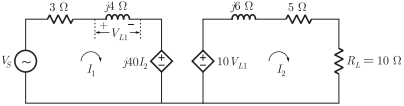
Q4. In the circuit shown below, if the source voltage  then the
Thevenin’s equivalent voltage in Volts as seen by the load resistance RL is
then the
Thevenin’s equivalent voltage in Volts as seen by the load resistance RL is
then the
Thevenin’s equivalent voltage in Volts as seen by the load resistance RL is
Answer : Option C
Explaination / Solution:
No Explaination.
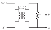
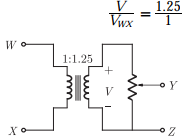
Q5. The following arrangement consists of an ideal transformer and an attenuator
which attenuates by a factor of 0.8. An ac voltage VWXI = 100 V is applied
across WX to get an open circuit voltage VYZ1 across YZ. Next, an ac voltage VYZ2 = 100 V is applied across YZ to get an open circuit voltage VWX2 across
WX. Then, VYZI/VWX1, VWX2/VYZ2 are respectively.
Answer : Option C
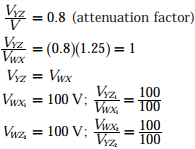
Explaination / Solution:
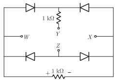
Q6. A voltage 1000 sin𝜔t Volts is applied across YZ . Assuming ideal diodes, the
voltage measured across WX in Volts, is
Answer : Option D
Explaination / Solution:
No Explaination.
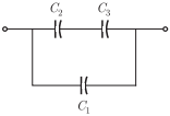
Q7. Three capacitors C1, C2 and C3 whose values are 10 μF , 5 μF , and 2 μF respectively, have breakdown voltages of 10 V, 5 V and 2 V respectively. For the
interconnection shown below, the maximum safe voltage in Volts that can be
applied across the combination, and the corresponding total charge in μC stored
in the effective capacitance across the terminals are respectively
Answer : Option C
Explaination / Solution:
No Explaination.
