Power Electronics - Online Test
Q1. For the circuit shown in the figure below, assume that diodes D1, D2 and D3 are ideal.
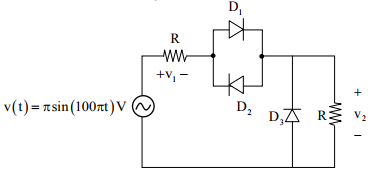
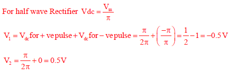
The DC components of voltages v1 and v2, respectively are
Answer : Option B
Explaination / Solution:
Q2. 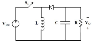
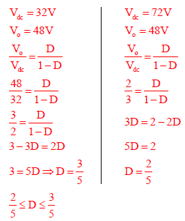
The input voltage VDC of the buck-boost converter
shown below varies from 32 V to 72 V. Assume that
all components are ideal, inductor current is
continuous, and output voltage is ripple free. The
range of duty ratio D of the converter for which the
magnitude of the steady state output voltage remains
constant at 48 V is
Answer : Option A
Explaination / Solution:
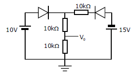
Q3. Assuming that the diodes in the given circuit are ideal, the voltage V0 is
Answer : Option B
Explaination / Solution:
No Explaination.
Q4. 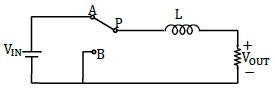
The power electronic converter shown in the figure has a single-pole double-throw switch. The pole P of the switch is connected alternately to throws A and B. The converter shown is a _______
Answer : Option A
Explaination / Solution:
No Explaination.
Q5. 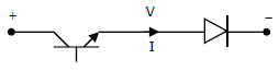
Figure shows a composite switch consisting of a power transistor (BJT) in series with a diode. Assuming that the transistor switch and the diode are ideal , the I-V characteristic of the composite switch is
Answer : Option C
Explaination / Solution:
No Explaination.
Q6. 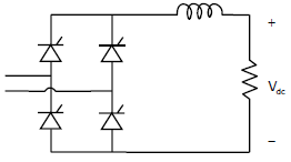
The fully controlled thyristor converter in the figure is fed from a single-phase source. When the firing angle is 0°, the dc output voltage of the converter is 300V. What will be the output voltage for a firing angle of 60°, assuming continuous conduction?
Answer : Option A
Explaination / Solution:
No Explaination.
Q7. The transistor circuit shown uses a silicon transistor with VBE = 0.7V, IC ≈ IE and a dc current
gain of 100. The value of V0 is
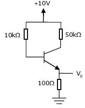
Answer : Option A
Explaination / Solution:
No Explaination.
Q8. 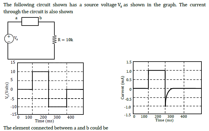
Answer : Option A
Explaination / Solution:
When diode is ON, i=1mA. When diode is OFF, i is zero after small reverse recovery time.
Q9. An SCR is considered to be a semi-controlled device because
Answer : Option C
Explaination / Solution:
No Explaination.
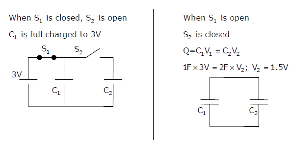
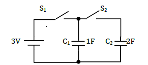
Q10. In the figure shown, all elements used are ideal. For time t<0, S1 remained closed and S2 open.
At t = 0, S1 is opened and S2 is closed. If the voltage Vc2 across the capacitor C2 at t = 0 is zero,
the voltage across the capacitor combination at t=0+ will be
Answer : Option C
Explaination / Solution: