Networks, Signals and Systems - Online Test
Q1. x(t)is a positive rectangular pulse from t = −1 to t = +1 with unit height as shown in the figure. The value of  { where X(ω) is the Fourier transform of x(t)} is
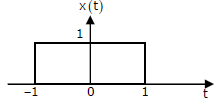
{ where X(ω) is the Fourier transform of x(t)} is
Answer : Option D
Explaination / Solution:
No Explaination.
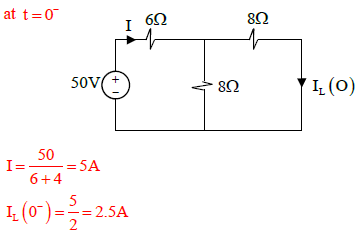
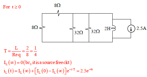
Q2. The switch in the figure below was closed for a long time. It is opened at t = 0. The current in
the inductor of 2 H for
t ≥ 0 is
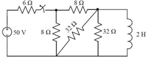
Answer : Option A
Explaination / Solution:
Q3. 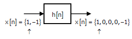
Given the finite length input x[n] and the corresponding finite length output y[n] of an LTI system as shown below, the impulse response h[n] of the system is
Answer : Option C
Explaination / Solution:
No Explaination.
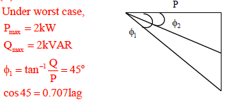
Q4. A load is supplied by a 230 V, 50 Hz source. The active power P and the reactive power Q consumed by the load are such that 1 kW ≤ P ≤ 2kW and 1kVAR ≤ Q ≤ kVAR . A capacitor connected across the load for power factor correction generates 1 kVAR reactive power. The worst case power factor after power factor correction is
Answer : Option B
Explaination / Solution:
Q5. The system ẋ = Ax + Bu with 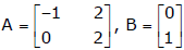 is
is
is
Answer : Option C
Explaination / Solution:
No Explaination.
Q6. The switch in the circuit has been closed for a long time. It is opened at t = 0. At t = 0+,
the current through the 1µF capacitor is
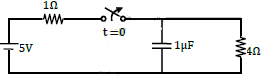
Answer : Option B
Explaination / Solution:
No Explaination.
Q7. 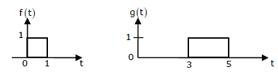
Given f(t) and g(t) as shown below:
g(t) can be expressed as
Answer : Option D
Explaination / Solution:
No Explaination.
Q8. As shown in the figure, a 1Ω resistance is connected across a source that has a load line v + i =
100. The current through the resistance is
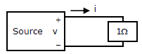
Answer : Option B
Explaination / Solution:
No Explaination.
Q9. Given f(t) and g(t) as shown below:

The Laplace transform of g(t) is
Answer : Option C
Explaination / Solution:
No Explaination.
Q10. 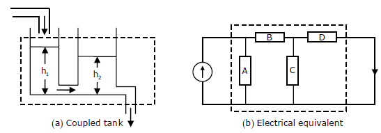
If the electrical circuit of figure (b) is an equivalent of the coupled tank system of figure (a), then
Answer : Option D
Explaination / Solution:
No Explaination.
