Networks, Signals and Systems - Online Test
Q1. 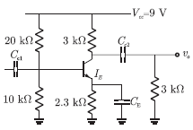
In the following transistor circuit,  , and 𝛽 and all the capacitances are very large
, and 𝛽 and all the capacitances are very largeThe value of DC current IE is
Answer : Option A
Explaination / Solution:
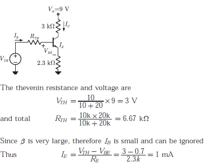
For the given DC values the Thevenin equivalent circuit is as follows
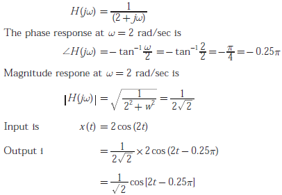
Q2. The impulse response h(t) of linear time - invariant continuous time system is given by h(t) = exp(- 2t)u(t), where u(t) denotes the unit step function.
The output of this system, to the sinusoidal input x(t) = 2 cos 2t for all time t , is
Answer : Option D
Explaination / Solution:
Q3. 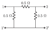
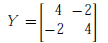
For the two-port network shown below, the short-circuit admittance parameter matrix is
Answer : Option A
Explaination / Solution:
Given circuit is as shown below
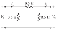
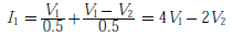
By writing node equation at input port
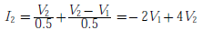
By writing node equation at output port
From (1) and (2), we have admittance matrix
Q4. For parallel RLC circuit, which one of the following statements is NOT correct ?
Answer : Option D
Explaination / Solution:
A parallel RLC circuit is shown below :
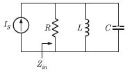
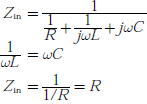
Input impedance
Q5.
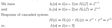
Two discrete time system with impulse response h1[n] = 𝛿[n - 1] and h2[n] = 𝛿[n - 2] are connected in cascade. The overall impulse response of the cascaded system is
Answer : Option C
Explaination / Solution:
Q6. 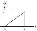
Consider the pulse shape s(t) as shown. The impulse response h(t) of the filter matched to this pulse is
Answer : Option C
Explaination / Solution:
Impulse response of the matched filter is given by


Q7. 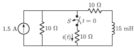
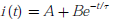
In the circuit shown, the switch S is open for a long time and is closed at t = 0. The current i (t) for t ≥ 0+is
Answer : Option A
Explaination / Solution:
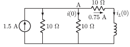
When the switch S is open for a long time before t < 0, the circuit is
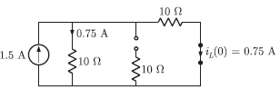
At t = 0, inductor current does not change simultaneously, So the circuit is
Current is resistor (AB)
i(0) = 0.75/2 = 0.375 A
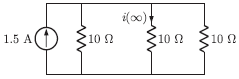
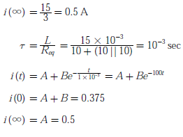
Similarly for steady state the circuit is as shown below
B = 0.375 - 0.5 =- 0.125
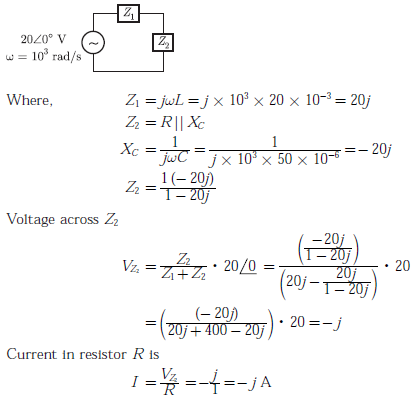
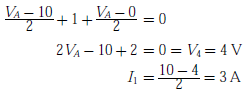
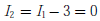
Q8. The current I in the circuit shown is
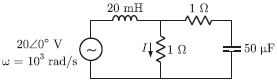
Answer : Option A
Explaination / Solution:
Q9. A continuous time LTI system is described by
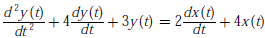
Assuming zero initial conditions, the response y(t) of the above system for the input  is given by
is given by
Answer : Option B
Explaination / Solution:
System is described as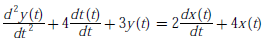
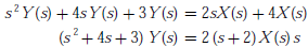
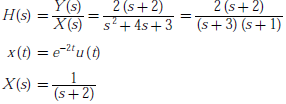
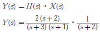
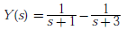
Taking laplace transform on both side of given equation
Transfer function of the system
By Partial fraction
Taking inverse laplace transform
Q10. In the circuit shown, the power supplied by the voltage source is
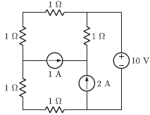
Answer : Option A
Explaination / Solution:
Applying nodal analysis
Current from voltage source is
Since current through voltage source is zero, therefore power delivered is zero.
